3D VFX experts used Eva & Spider to develop a Sleepy Hollow character
Summary: The special effects team working on an episode of the popular series Sleepy Hollow needed to create a highly-lifelike digital double of an actor wearing a very specific and unusual costume.
The Goal: To use a handheld 3D scanner and create a realistic digital double of a fantasy character. The final results should be so lifelike that viewers don’t doubt that what they’re seeing on the screen is the costumed actor himself.
Tools Used: Artec Eva, Artec Spider, Artec Studio
Want to know how Artec scanners deal with hard-to-scan black surfaces? Let’s hear from Second Chance Games & Visual Effects, who scanned an actor in a very sophisticated robe for an episode of the TV series Sleepy Hollow. Second Chance Games & Visual Effects is an Atlanta based media provider of digital assets for the games, visual effects, and 3D visualization industries.
The digital double of Wraith, with and without texture
“The robe he was wearing was made of different fabrics. Some of the robe was mesh-like, where you could see through it,” said Vic Holt, Vice President of 2cgvfx. “To some degree it was shiny and black...two very difficult things to address in a scan!”
Vic attempted to scan the robe using standard settings, but then realized some of them needed to be tweaked. “The settings had to be changed on the texture brightness, bringing it down a small amount to take the glare off, so the scanner could see better. Also, we adjusted the sensitivity up some and just had to move slow,” said Vic.
The area to capture was quite large, and the team had to scan in sections with plenty of overlap, so alignment could be done well. They used Eva for the robe and Spider for facial areas with great detail.
Second Chance Games & Visual Effects was introduced to both scanners by Artec Certified ResellerRapid Scan 3D. In the words of Chris Strong, President of Rapid Scan 3D, “Eva and Spider have been two of the most popular handheld 3D scanners on the market, from CGI to aerospace, archaeology, reverse engineering, and beyond. If you’recapturing medium-sized objectsand reliable, high-resolution results are vital, you need to check out Eva. The Artec Eva is amazing for scanning people and body parts and that’s what Second Chance Games & Visual Effects needed. Talking about Spider, where thisultra-resolution 3D scannertruly soars is when you need to capture tiny details or complex geometries. This can mean printed circuits, machine parts, dental components, jewelry, and that’s just a brief list.”
Vic Holt shared a few details about the scanning process, “The robe weighed a good bit, and we had the actor stand on a turntable with poles to rest his hands on, keeping his elbows locked into position.” He continued, “We knew going in that the robe would probably fall off our very large turntable, so I went to our shop and cut a larger piece of wood to be affixed to the top of it, to hold the extra cloth material instead of it dragging on the floor when we spun him.”
Vic also used a special handle hooked to the scanners on one side, and on the other side there was a small monitor hooked to the HDMI port of the computer. “It allowed me to see what I was scanning rather than having to look over at the computer,” said Vic. “I just mirrored over the display and had Artec doing a Real Time Fusion while saving the raw scan file in the background.”
Vic Holt using a special monitor fixed to Eva during a scanning session.
After scanning the robe, the team had to remove it and do more scanning of his body, just in case the robe moved and the chest area would be exposed. “So we basically had two separate scans to work on….the robe and the guy underneath it,” said Vic.
Then the models were rebuilt and remeshed in ZBrush, so they could be altered and animated. “The mesh work needs to be done in a way that is optimized for animating as well as in not hindering during the rendering phase,” said Vic. “We provide the model as optimized as possible, so it’s easy to deal with by the VFX department.”
A still of Wraith in Season 3 Episode 02 of Sleepy Hollow.
“It’s been real fun creating digital doubles of wonderful creatures this show has developed,” said Vic. “Their attention to detail is quite evident in watching the show, as my wife and I have done since its beginning.”
Girl Gang Garage: Custom Car Rebuilds + 3D Scanning + 3D Printing
What do you get when you cross a 1961 Volvo PV544 retro-look car with a sleek 2019 Volvo S60 T8 Polestar Engineered sedan – and why would you ever do that?
You get a custom head-turner hybrid vehicle designed to get people talking, especially about women in automotive trades. That’s because this blended vehicle project is being disassembled, redesigned and rebuilt by an all-female team based atGirl Gang Garagein Phoenix Arizona.
Bogi Lateiner and Shawnda Williams, co-owners of Girl Gang Garage, stand next to the stripped-down body of a 1961 Volvo PV544 that will soon be retrofitted on the chassis of a brand-new 2019 Volvo S60 T8 Polestar Engineered sedan. The rebuild project provides a rare hands-on learning opportunity for women of all ages and skill levels, from around the U.S., to come and learn (or improve) skills in welding, cutting, transmission work, body repair/painting, electronics, upholstery and more. (Image courtesy Girl Gang Garage.)
Girl Gang Garage founder and co-owner, Bogi Lateiner, TV host ofMotortrend’s All Girls GarageandGarage Squadshows, is well on the way to transforming these vehicles as the third major public project she has undertaken. Along with co-owner Shawnda Williams, Lateiner offers women of all ages, experiences and skill levels the chance to lend a hand, learn a tool, and possibly discover a new career-path in the automotive trades.
The front showroom of Girl Gang Garage (Phoenix AZ). At the left is the group’s second all-female build dubbed High Yellow 56, displayed at the 2019 SEMA Show. Partially hidden in the center is the first (2017) Girl Gang build, the Chevy Montage with its BMW engine, and at the right is the early-stage PV544 rebuild slated for showing at the 2023 SEMA Show. (Image courtesy PADT Inc.)
Lateiner and Williams apply well-honed old-school skills but have been increasingly interested in the possibilities offered by today’s digital workflow. That’s why early in 2021, after conversations with the fellow re-build team atKindig-It Custom Car Fabrication, Lateiner reached out to Chris Strong with Rapid Scan 3D to see how they might work together to incorporate 3D scanning into their project
The team at Rapid Scan 3D including Chris Strong, 3D Scanning Specialist and Hayati Dirim, Lead Application Engineer were immediately onboard with the chance to help Girl Gang Garage move into the digital world while widening their circle of women with automotive skills and interests. Rapid Scan 3D was able to utilize 3D scanning data from the original vehicle and Reverse Engineer the front end using class leading software Geomagic Design X from Oqton. Hayati was able to take the CAD data deliver a CAD ready surface model to the team at All Girl Garage.
A Virtual Team and a Digital Workflow
One of the amazing parts of this build is that included members ofWomen in 3D Printingoffered to coordinate many of the publicity efforts and even sponsor a related design competition targeted at young women in high schools and colleges who are learning CAD skills. (More on that to come.)
During the first few Zoom meetings that introduced Lateiner and Williams to the technical capabilities of the different team members and the printer, the basic rebuild plan was presented: strip the PV544 down to bare metal (removing every mechanical and electrical component), disassemble the S60 down to the chassis, engine, drive-train and hybrid motor system, and figure out how to make the two sections fit!
Traditionally, that workflow depended strictly on the classic tools of the trade, from cutting wheels and a Sawzall to hand-grinders and pneumatic drills. Those components are still coming into play on the current project under the skilled eye of the Girl Gang Garage leaders, but now complementary digital processes are being added.
It Starts with Scanning
3D Scan Data (Image courtesy Rapid Scan 3D)
Surfaced / CAD Data inside Geomagic Design X (Image courtesy Rapid Scan 3D)
The scan data, if exported as an STL file, could be sent directly to a surfacing package such as Geomagic Design X. This software tools let users convert the STL mesh into an IGES surface, which can then be brought into a CAD package as the basis for a new solid model.
Scanning has many other purposes and capabilities. If CAD data were available for the actual vehicle, those files could be imported, overlaid on the captured data, and compared, alerting the user to deviations between intended and actual dimensions – a very common use in Geomagic Design X and Control X.
Next Steps
Every Thursday through Sunday, volunteer women come to Girl Gang Garage and learn to use cutting tools, welders, sanders and more, making daily progress toward the completed hybrid PV544. (All women are invited to come help and learn, at no cost – justsign up to get involvedand get yourself to Phoenix.) Here are a few glimpses into the work as of early April – much more has been done but stay tuned for the next blog post as we show off elements of the S60 sedan, scan data being used for reference, and details of the design contest.
Views of the PV544 Volvo with work underway on a rear fender, with Bogi Lateiner in her Girl Gang Garage location). (Images courtesy PADT Inc.)
Let's see the results.
Resized, reupholstered dashboard of Girl Gang Garage’s Iron Maven Volvo custom car-rebuild project. (Image courtesy PADT Inc.)
The Iron Maven at SEMA 2022; note the re-used S60 sunroof and hybrid charging-port (front left fender). (Image courtesy Anne Pauley)
The Iron Maven at SEMA 2022, showing the packed engine compartment, extended fenders, new headlamps and cool grill. (Image courtesy Anne Pauley.)
Bogi Lateiner and Anne Pauley at SEMA 2022. (Image courtesy Anne Pauley.)Girl Gang GarageThe mission of Girl Gang Garage is to elevate, encourage, and champion women’s entry and advancement within the automotive & skilled trade industries. Inspire women to discover and build confidence in their own talents, remove barriers, and provide a safe, supportive environment to explore opportunities within the welding, automotive service/repair, paint, and body industries.www.https://girlganggarage.com
Are you a fan of the Big Bang Theory? We are! Those geeky, nerdy, awkward, but lovable guys often remind us of...well...us! And last season on the show, those boys finally caught up with us. They stumbled onto 3D scanning/printing.
In Season 6, Episode 14 (called the "Cooper/Kripke Inversion"), Howard Wolowitz and Raj Koothrappali ordercustomized figurinesof themselves online. When the toys arrive, they are quickly disappointed at how little the dolls resemble them. Raj suggests buying a used 3D Printer and doing the job right. They scan themselves and Bernadette with a Kinect sensor and manufacture perfect replicas of each other in color.
Image courtesy of Warner Bros. Television
The episode as hilarious, but there is a dark secret... Fact of the matter is, the real scanning was done with an Artec Eva3D scanner, not a Kinect sensor. The scans done with Kinect didn't have the right resolution/texture for a quality, color 3D print. Artec's authorized reseller, Chris Strong from Rapid Scan was invited to the set to do the scanning.
Take a look at the behind the scenes photos...and then check out the scans of Howard and Bernadette.
Challenge:An Academy Award-winning special effects makeup artist needed to find a better way to lifecast actors than via the traditional silicone-based process.
Solution:Artec Leo, Artec Space Spider, Artec Studio, ZBrush
Result:No longer do actors need to sit perfectly still for 20-30 minutes with their faces smothered in silicone. In just 1-2 minutes, their faces or other body parts are 3D scanned with Leo and Space Spider, capturing everything down to the finest wrinkles and tiniest pores.
Why Artec 3D:The compact and fully portable Artec 3D scanners make it possible to create incredibly lifelike lifecasts that can be 3D printed and sculpted to perfection in a fraction of the time that traditional methods demand.
Kazu Hiro in his studio, scanning model Jack Currier with Artec Leo. Image courtesy of Kazu Hiro
Kazu Hiro, renowned for his remarkable makeup artistry, has sculpted the faces of Hollywood’s elite, masterfully transforming them into unforgettable characters on the silver screen.
From the recent run of Oscar-nominated films, Hiro worked with A-listers such as Bradley Cooper and Robert Downey Jr. for 2023 hit Maestro. His previous work includes blockbusters such as Bombshell, Darkest Hour, Salt, The Curious Case of Benjamin Button, Men in Black II, How the Grinch Stole Christmas, and other top movies.
Hiro’s carefully cultivated talent has been recognized numerous times, including with multiple Academy Awards for Best Makeup and Hairstyling, BAFTA Awards, and various other accolades.
3D-printed Leo HD Mode and Space Spider scans. Image courtesy of Kazu Hiro
With his seemingly tireless goal of perfection, Hiro constantly strives to advance his mastery of special effects makeup artistry to new heights, which means always being on the lookout for new ways to enhance his design and creation workflow.
The special effects makeup and fine art of Kazu Hiro
Lifecasting, a cornerstone of Hiro’s makeup artistry for years, is a detailed process of creating a three-dimensional copy of a living human body, regularly called upon in the movie industry to achieve high levels of realism in character makeup.
This meticulous method starts with preparing the subject and gathering the necessary materials, including silicone rubber.
Despite its advantages, such as being relatively affordable, capturing fine skin details, and creating a durable, reusable cast, traditional lifecasting has several downsides. First of all, the process is often time-consuming and messy, uncomfortable at best, and sometimes even bringing on claustrophobia in the actor.
What’s more, distortions in the final cast can arise due to the weight of the mask pulling down on the face, or the actor’s involuntary movements as they’re forced to sit still for so long, either of which can drastically affect the end results.
Turning towards 3D scanning
Hiro’s journey for a better solution to traditional lifecasting led him to the world of 3D scanning, and ultimately to his local Artec AmbassadorRapid Scan 3D. Here, he met Chris Strong, a recognized 3D scanning expert in the movie industry and beyond, who introduced Hiro to theArtec Space Spider.
Silicone nose cast, undercuts treated, ready for scanning with Artec Space Spider. Image courtesy of Kazu Hiro
A long-standing favorite among creatives and engineers alike, the Space Spider is an ideal tool forCGI work, owing to its ultra-high-resolution capabilities and the potential to capture every minute detail of an actor’s face in color 3D with jaw-dropping precision.
The Space Spider brought about an immense shift in Hiro’s workflow. He was able to let go of the messy and uncomfortable traditional lifecasting process, switching to non-contact 3D scanning without sacrificing anything when it comes to realism.
For capturing fine details, such as the tiniest wrinkles around the eyes, pores, and minute facial contours, Hiro now turns to the Space Spider.
For capturing larger aspects of an actor like the overall head, neck, and body, Hiro uses theArtec Leo. Its high FPS capture rate, wide field of view, ease of use, and wireless capability make it ideal for broader scans, along with the rich detail made possible with Leo’sHD Mode.
Detail capture comparison: Model of Robert Downey Jr. made with photogrammetry (left) and Artec Space Spider and Leo (right).Imagecourtesy of Kazu Hiro
The 3D scanning process takes a mere 1-2 minutes, drastically faster than the 20-30 minutes required for traditional lifecasting. And, unlike many 3D scanners, Leo and Space Spider are entirely non-contact, requiring no targets or markers, thereby eliminating any chance of discomfort.
Crucially, these two scanners integrate seamlessly in Artec Studio. Multiple 3D scans from both the Leo and Space Spider import into the same workspace with one click, allowing Hiro to create the most detailed, comprehensive 3D models of an actor’s face, head, neck, and body.
Combined Leo HD Mode and Space Spider scans of Sean Penn. Image courtesy of Kazu Hiro
For the CGI and film industry, scanning on location at a moment’s notice has become a reality, what with Leo’s portability and ease of use, and Space Spider’s stunning dedication to every detail. And for each and every project, the final result is a vividly lifelike digital replica that serves as the perfect blueprint for Hiro’s extraordinary makeup transformations.
“Kazu’s work is second to none, and his quest for perfect representation called for an equally superior tool. The Artec Leo’s accuracy, ease of use, and portability all made it the right fit. I confidently recommended it to Kazu, knowing it would transform his craft and elevate the quality of his work,” said Chris Strong, a 3D scanning specialist at Rapid Scan 3D.
Turning 3D scans into true-to-life special effects makeup
The actual transformation from 3D scan to makeup prosthesis is an exacting process. Following scanning, Hiro turns toArtec Studio, an innovative software solution for 3D scan data processing, with a rich toolset to optimize and refine the 3D scans of the actor, enhancing every minute detail for the most accurate representation.
From Artec Studio, Hiro exports the 3D scans to ZBrush, where he puts the finishing touches on the 3D model of the actor’s face, head, or other body part, after which he 3D prints the lifecast and then physically sculpts it with clay.
Combined Leo HD Mode and Space Spider scans in ZBrush. Image courtesy of Kazu Hiro
Application of the prosthesis is an art in itself. Each piece, built upon the detailed realism of the actor’s face or other body part, as captured by the Leo and Space Spider, is carefully applied and fixed to the actor’s skin, creating a seamless transition that blurs the line between reality and fantasy.
3D print from neck mold scan made with Artec Leo HD Mode and Space Spider. Image courtesy of Kazu Hiro
Throughout the filming process, Hiro monitors the prostheses, ready to make adjustments or replacements anytime. By integrating the Artec 3D scanners into his workflow, Hiro has reinvented the art of special effects makeup creation, synergizing technology and painstaking craftsmanship to an unprecedented degree.
The impact of 3D scanning on Hiro’s work
Hiro said, “The Artec Leo and Space Spider have altered my work profoundly. This technology gives me an exceptional level of detail, without the distortions or actor discomfort that might arise during traditional lifecasting.”
He continued, “These scanners have been more than just tools for me. They are truly groundbreaking in the arena of special effects makeup.”
3D-printed bust of Richard Krueger, from Leo HD Mode and Space Spider scans. Image courtesy of Kazu Hiro
As an avant-garde in the industry, Hiro eagerly anticipates the future of his craft. He said, “I look forward to the new advancements that Artec will bring to 3D scanning technology. These innovations will continue to push the boundaries, allowing me to further enhance my Hollywood makeup work as well as my fine art sculptures.”
Summary: The world's most productive ongoing source of Ice Age fossils needed to digitally capture bones from dire wolves, sabre-toothed cats, ground sloths, mammoths, and more, quickly and easily.
The Goal: To use a handheld, high-resolution color 3D scanner to capture fossils of all shapes and sizes in minutes, then archive the 3D models for preservation, research, and future public outreach.
Tools Used: Artec Space Spider, Artec Studio
12,000 years ago, the very heart of Los Angeles, California had large reserves of natural asphalt (aka ‘tar’) deposits lurking beneath the surface of the ground. Not to mention at the bottom of streams and ponds. When animals such as mammoths, bison, horses, ground sloths, and camels ventured down to the water to quench their thirst, they would occasionally get stuck in the extremely sticky asphalt that had seeped up to the surface. As little as 1.5 inches (4 cm) of liquid asphalt was enough to entrap a bison or even a mammoth.
Dire wolf skeleton unearthed from La Brea Tar Pits
Predators, including dire wolves (Canus dirus), sabre-toothed cats (Smilodon fatalis), and American lions (Panthera leo atrox), saw them helplessly struggling in place and closed in for what they thought would be an easy meal. Soon both predator and prey were mired in the unforgiving asphalt, where they would both die of starvation and slowly decay on the surface, with some of their remains eventually buried over time in asphalt-saturated sediments.
Sabre-toothed cat skeleton in the museum at La Brea Tar Pits
The museum at La Brea Tar Pitsis home to a collection of fossils that have been unearthed from those same still-bubbling asphalt deposits since scientists first began studying them in 1906. All in all, more than 3.5 million specimens have been discovered at La Brea Tar Pits over the years. These fossils have been radiocarbon dated to as much as 50,000 years old.
The museum at La Brea Tar Pits
The Tar Pits have been aliteral treasure trovefor paleontologists the world over, with massive numbers of well-preserved specimens discovered. To give one example, they’ve unearthed the remains of more than 3,600 dire wolves alone, in addition to the tens of thousands of other fossils the asphalt has offered up.
Pit 91 at the La Brea Tar Pits
Researchers have been conducting a number of studies on the specimens for years now, including radiocarbon dating and other molecular analyses that provide data on biotic changes over time that can be correlated to environmental changes and human impact. Radiocarbon dating allows them to put a precise date on these ancient plants, insects, birds, reptiles, amphibians, mammals, and shells, and gradually develop a much clearer view into what the local environment was like thousands of years before humans arrived and settled.
This is crucial not merely for the sake of understanding the past, but also to help scientists interpret more accurately the changes taking place in today’s environment, as well as to better predict what may be to come in the decades and centuries ahead, and to assist with conservation planning.
Fossils found in Pit 91, one of more than 100 pits at La Brea Tar Pits
Prior to the radiocarbon dating, which is a type of destructive testing, the museum would make plaster casts of fossils, so as to preserve the originals for study. Photogrammetry with a DSLR camera was also briefly employed for each specimen, which entailed lengthy processing times and a huge backlog of fossils waiting in shelves and boxes.
Shelves of fossils in storage at The La Brea Tar Pits Museum
Then they learned about 3D scanning being used in paleontology, how it significantly accelerates workflows while at the same time heightening accuracy and opening up a range of possibilities using 3D printing and visualization, in addition to it unlatching the doors to digital archival.
American lion skeleton in the museum at La Brea Tar Pits
The 3D scanning specialists at Artec Certified ResellerRapid Scan 3Dintroduced them to theArtec Space Spider, a professional handheld structured-light scanner that quickly creates metrology-grade 3D models of objects, even those with complex organic shapes, such asfossils. Boasting an accuracy of up to .05mm, in mere minutes Space Spider does what used to take up to an hour or more per fossil.
Chris Strong of Rapid Scan 3D said, “When we looked at the levels of detail that La Brea Tar Pits needed for 3D scanning fossils and bones, it was apparent that the Artec Space Spider was the right choice. The Space Spider is portable and easy to use, for everyone from beginners to advanced users. We're able to capture high-resolution data with color information within minutes. We have been implanting the Artec scanners in the aerospace and medical industry for years with great success as well. The same technology can be used for heritage preservation as well as scanning bones and fossils.”
Carrie Howard holding a camel’s 6th cervical vertebra unearthed from the asphalt
In the words of La Brea’s Imaging Specialist Carrie Howard, “Space Spider accurately captures the complex geometries of bones. Some of these shapes and surface characteristics are challenging to capture, from the sweeping curves of a bison’s rib, to the long maxillary canine teeth of a sabre-toothed cat, as well as the short-faced bear’s metatarsals, and so many more examples I could name...Space Spider lets us capture it all in perfectly lifelike, high-resolution color 3D.”
Howard went on, “one of our initial projects included 400 specimens. We scanned and processed those quickly, and then continued on with others. Now we’re able to handle so many more specimens than we ever used to in the past, whereas with photogrammetry, the time it took for this quantity of specimens was more than three times as long.”
Dire wolf vertebra discovered during the Museum’s excavationProject 23
Howard’s process for 3D scanning with Space Spider takes a few minutes in most cases: she simply places a specimen onto a small turntable, picks up Space Spider, then slowly rotates the turntable as she moves the scanner up and down, thereby capturing every facet and surface. During the process, the scanner’s software,Artec Studio, displays the scan in real time as it takes place. If any spots are missed, it is immediately visible, and the area can easily be scanned once again. The specimen is then turned over and the process is repeated.
3D scanning a dire wolf jawbone with Artec Space Spider
Post-processing takes place in Artec Studio, which entails aligning and registering the scans into a unified, “perfect digital replica” 3D model, which is then exported as an OBJ file and archived.
3D model of Dire wolf jawbone, scanned by Artec Space Spider
Recently the Museum tested theArtec Micro, an automated metrology-grade desktop 3D scanner designed for scanning small objects at up to 10 microns’ accuracy. The Museum has an extensive collection of small specimens, from a variety of plants and animals including bird bones, freshwater snails, and a wide range of seeds. The scanning workflow is easy: they simply mount a specimen on Micro’s scanning platform, and after a few mouse clicks, the scanner takes care of the rest. The platform swings and rotates while Micro’s structured blue light and twin cameras capture every characteristic of the specimen’s surfaces from all possible angles.
As seen in the above photo, Museum visitors are welcome to observe Space Spider in action from the other side of the glass, alongside a screen displaying the 3D scan of the fossil in real time (via Artec Studio). Across from the 3D scanning window is the Museum’sFossil Lab, playfully nicknamed, the “Fishbowl,” a semi-circular, glass-enclosed lab where children and adults alike can watch paleontologists up close as they sift through, clean, and catalog a wide variety of fossil finds.
Recreation of a mammoth and sabre-toothed cat trapped in asphalt, fromTitans of the Ice Age
Considerations and talks about an online 3D-model specimen database for researchers near and far, as well as various types of local and virtual public outreach, including for schools and universities, have been points of focus for the Museum, and will continue.
Two additional projects, currently in the exploration and development stage, will utilize AR (augmented reality) to heighten public engagement with La Brea Tar Pits’ paleontological resources via interactive and immersive exhibits. Such projects would greatly benefit from the 3D models created with the Museum’s Space Spider, together with other digital technologies, for increasing the public’s knowledge of science and reducing scientific misconceptions at all levels of society.
Artec Jet 3D Scanner: High-Speed SLAM LiDAR for Large-Scale 3D Mapping, Digital Twins, and Reality Capture
Artec Jet: A New Level of Mobile LiDAR 3D Scanning
The Artec Jet is a high-precision, mobile SLAM-based LiDAR 3D scanner built for capturing large environments quickly, accurately, and safely. Designed for applications where traditional 3D scanning or stationary tripod scanning may be too slow or difficult to deploy, Artec Jet brings fast reality capture to facilities, construction sites, tunnels, infrastructure, mines, roadways, industrial plants, and other large-scale environments.
Unlike traditional static terrestrial laser scanners that require multiple tripod setups, Artec Jet allows users to scan while moving. The system uses SLAM technology, which stands for Simultaneous Localization and Mapping, to capture 3D data while continuously tracking its position in the environment. This makes it especially valuable for GPS-denied locations such as indoor facilities, underground mines, tunnels, industrial spaces, and enclosed structures. Artec lists Jet as a high-speed mobile LiDAR mapping system capable of capturing facilities, infrastructure, and sites in minutes rather than hours.
Built for Large-Scale Digital Twins
Artec Jet is ideal for creating digital twins of large environments. Whether documenting an industrial facility, scanning a building for renovation, capturing a mine tunnel, or mapping a roadway, Jet provides the speed and coverage needed for full-site data capture. Artec lists key applications including digital twins, as-built documentation, volumetric measurement, clash detection, inspection, Scan to BIM, facility management, progress monitoring, and site planning.
For companies that need accurate 3D data of large spaces, Jet can reduce field time and improve safety by allowing teams to capture data in fewer passes. Instead of measuring manually or setting up a tripod scanner in multiple positions, operators can walk, drive, fly, or mount the scanner depending on the job.
Seven Deployment Modes for Maximum Flexibility
One of the biggest advantages of Artec Jet is its versatility. The same scanner can be used in multiple ways depending on the environment and project requirements. Artec lists seven deployment modes: handheld, backpack, drone, vehicle, cage, telescopic pole, and robot.
This makes Jet a flexible solution for a wide range of industries:
Handheld scanning is ideal for buildings, rooms, confined spaces, industrial facilities, and quick site documentation.
Backpack scanning allows hands-free mapping for longer surveys or large walking routes.
Drone deployment helps capture dangerous, elevated, or hard-to-reach areas while keeping operators safely away from hazards.
Vehicle mounting is useful for roadways, tunnels, large facilities, and long linear assets.
Robotic integration allows the scanner to be mounted on platforms such as inspection robots for hazardous or restricted environments.
Telescopic pole deployment helps reach ceilings, voids, shafts, and tight areas where drone access may not be practical.
Protective cage deployment is designed for vertical shafts, voids, and enclosed areas where the scanner needs added protection.
GPS-Free Scanning for Difficult Environments
Artec Jet is designed to work in environments where GPS is not available. This is a major advantage for underground mining, indoor facilities, tunnels, public safety, defense, industrial plants, and infrastructure inspection. Artec states that Jet uses SLAM algorithms to deliver positioning without satellites, making it suitable for GPS-denied environments.
Because LiDAR is an active sensing technology, Artec Jet can also operate in zero-light or low-light environments. This is important for mines, tunnels, night operations, sealed buildings, and other locations where visible light is limited or unavailable.
Speed, Accuracy, and Coverage
Artec Jet is built for fast data capture. Artec lists a scan speed of up to 1.9 million points per second, a scanning range of 0.5–300 meters, and global accuracy of up to 5–10 mm, depending on the workflow and environment.
For mapping, the scanner provides ±15 mm accuracy in general environments and ±10 mm accuracy indoors or underground, with ±5 mm change detection capability. This makes it a strong fit for projects where users need accurate, repeatable 3D data for monitoring, documentation, inspection, and comparison over time.
Real-Time Feedback and On-Site Verification
One of the key workflow advantages of Artec Jet is the ability to preview point cloud data during capture. Artec states that Jet streams live point cloud previews to a companion app, helping operators verify coverage while still on site.
This is important because missed data can be expensive. If a team leaves a job site and later discovers gaps in the scan, they may need to return for additional capture. With real-time feedback, users can confirm coverage before leaving the site, helping reduce costly rework.
Optional Color Capture and Artec Twins Workflow
By default, Artec Jet captures accurate LiDAR point clouds with intensity data. For true-color RGB point clouds, Artec lists an optional action camera workflow that allows color imagery to be aligned with the point cloud in processing.
Artec Jet data is processed in Artec Twins, a platform built for large-scale 3D data. Artec describes the workflow as processing raw scans into accurate point clouds, georeferencing data with ground control points or RTK, merging multiple scans, visualizing 360° colorized data, and analyzing results for change detection, measurements, and scan-to-BIM workflows.
Where Artec Jet Fits in the Artec 3D Ecosystem
Artec Jet is designed for large environments, while other Artec scanners can be used to add detail at the part or component level. For example, Artec Leo can capture detailed geometry and texture on medium to large objects, while Artec Ray II can provide high-accuracy long-range stationary scans. Artec notes that Jet, Ray II, and Leo can work together as part of a complete pipeline for digitizing everything from full sites to individual components.
This makes Jet especially valuable for customers who need both site-level context and high-detail component capture. A facility, vehicle, machine, production line, building, or structure can be captured at scale with Jet, then more detailed areas can be supplemented with other Artec scanning systems.
Industries That Can Benefit from Artec Jet
Artec Jet is a strong solution for industries that need fast and accurate reality capture over large spaces. This includes:
Architecture, Engineering, and Construction: As-built documentation, progress monitoring, Scan to BIM, site planning, and renovation projects.
Mining: Underground tunnel mapping, stopes, shafts, headings, volume calculations, and hazardous area capture.
Oil and Gas: Refineries, pipelines, offshore platforms, flare stacks, and industrial asset inspection.
Defense and Security: GPS-denied mapping, tunnel documentation, tactical 3D data capture, and robotic or drone-based inspection.
Public Safety: Disaster scenes, collapsed structures, accident documentation, and unsafe environments where remote capture improves safety.
Industrial Plants: Facility documentation, equipment layout, maintenance planning, clash detection, and digital twin creation.
Why Buy Artec Jet from Rapid Scan 3D?
Rapid Scan 3D helps customers select, implement, and support professional 3D scanning technology for real-world applications. As an experienced Artec 3D reseller and 3D scanning solutions provider, Rapid Scan 3D can help determine whether Artec Jet is the right fit for your workflow, environment, accuracy requirements, and deliverable needs.
From demonstrations and training to software recommendations and workflow development, Rapid Scan 3D can support customers looking to capture everything from large facilities and infrastructure to individual parts, assemblies, and inspection data.
Contact Rapid Scan 3D to schedule a demo or discuss whether Artec Jet is the right solution for your application.
Introducing Mingda 3D Printers & New Partnership with Rapid Scan 3D
Introducing Mingda 3D Printers & New Partnership with Rapid Scan 3D
The Power of Mingda in Additive Manufacturing
Mingda 3D, founded around 2012, has rapidly emerged as a prominent global brand of industrial-grade FDM 3D printers. Their lineup—including standout models like the MD-400D, MD-600D, and MD-1000D—prides itself on offering large build volumes, ** ID EX dual extruder capabilities**, and high-speed printing tailored for professional applications
The MD-400D brings features such as a spacious 400 × 400 × 400 mm build area, up to 350 °C high-temperature hot ends, and Klipper firmware enabling speeds up to 300 mm/s. It supports four versatile modes—Duplicate, Mirror, Dual-Color, and Support—boosting productivity and design flexibility. For even bigger needs, the MD-600D and MD-1000D offer equally fast speeds, massive volumes (up to 1 m³!), and precision mechanisms like X/Y guide rails and closed-loop motors.
These printers serve various industries—automotive, aerospace, medical, prototyping—in both small-batch and complex end-use manufacturing. Reliability is also key: the MD-400D helped Insculp3d dramatically reduce print scrap and ensure zero-waste, high-efficiency production, thanks to Mingda’s optimized slicer and stable printing process.
Rapid Scan 3D: Enhancing the Client Experience
Rapid Scan 3D, a company bringing over a decade of expertise in 3D scanning and 3D printing is excited to partner with Mingda 3D printers. Rapid Scan 3D bridges the gap between digital designs and physical outputs—providing clients with tailored workflows from precise scanning, quality modeling, to flawless printing on Mingda machines.
Expert consultation: Rapid Scan 3D reviews project requirements and recommends the right Mingda model and filament for optimal results.
Seamless integration: They ensure scans translate cleanly into printable models and leverage features like dual colors, mirrored outputs, or efficient support strategies that Mingda’s IDEX systems excel at.
Technical support & training: With deep experience in handling complex prints and scanners, they provide end-to-end support—from resolving tricky slicer settings to fine-tuning print modes for advanced engineering filaments.
This collaboration means clients benefit from Mingda’s industrial-level printing prowess, combined with Rapid Scan 3D’s decade-strong expertise, ensuring every project achieves precision, efficiency, and creative freedom.
Summary
Mingda delivers industrial-grade 3D printing with large volumes, fast speeds, dual-extrusion versatility, and dependable performance.
Rapid Scan 3D complements that with seasoned scanning, modeling, and consulting services, ensuring clients seamlessly convert ideas to reality.
Together, this partnership empowers businesses, educators, and creatives to leverage additive manufacturing with confidence and ingenuity.
Ready to learn more? Contact us today to discuss your 3D printing needs
President Barack Obama scanned with Artec Eva to create first ever 3D presidential portrait
President Barack Obama scanned with Artec Eva to create first ever 3D presidential portrait.
Challenge: To capture the 44th President of the United States likeness using 3D tech, thus creating the first ever 3D presidential portrait of a US leader.
Solution: Artec Eva, Artec Studio
Results: The very first 3D-printed bust and life mask of a US president, as well as photorealist 3D models
Former US President Barack Obama’s time in office was a tenure of firsts. And in 2014, when he sat down to have his presidential portrait taken, he added another to his long list of accomplishments. This one might not rank quite as high up the list as his Nobel Peace Prize, but all the same the 44th POTUS made history by being the first to have his presidential portrait produced using 3D scanning.
The project, created by a Smithsonian-led team of 3D-digital-imaging specialists, drew inspiration from Abraham Lincoln’s life mask, molded nearly two centuries prior. The two leaders’ experiences, however, were very different. And that contrast is emblematic of the progress technology has made in that time.
President Lincoln had a plaster cast placed over his face and reportedly had to wait for about an hour for it to set before it could be removed. The commander in chief had to breathe through holes in the cast (some accounts say through straws in his nostrils!) while he waited.
The Lincoln life masks, the last of which was molded just two months before his assassination in 1865, inspired the Smithsonian project.
Removing the mold once it had been set was a process Lincoln is said to have described as “anything but agreeable.” Leonard Wells Volk, the sculptor who created the first Lincoln life mask in 1860, described how the plaster cast “clung pretty hard.” And with an artist’s typical concern first for his works, he wrote about how the mold was “all in one piece, with both ears perfectly taken,” and added that “it hurt a little, as a few hairs of the tender temples pulled out with the plaster and made his eyes water.”
Fast forward just over a hundred and fifty years and President Obama strides into a room to sit in front of a lighting rig right under, as it happens, a portrait of Abraham Lincoln. He holds his presidential pose, and an array of 50 custom-built LED lights, eight high-res sports photography cameras, and six additional wide-angle cameras fire off over a period of about one second.
He then turns away from the lights and cameras and sits still for about 90 seconds as two digitization professionals capture his likeness using Artec Eva, a powerful structured-light 3D scanner that is capable of capturing and simultaneously processing up to 18 million points per second, with an accuracy of up to 0.1 mm. From the moment the president enters the room, the whole thing is done in about 7 minutes.
Lincoln looks on wistfully.
Ideal for scanning both medium-sized objects and people, Artec Eva captured every feature of the president.
The Smithsonian turned to Artec Ambassador and Artec Gold Reseller Rapid Scan 3D for implementing this technology into their 3D Digitalization Team.
“There is truly no better 3D scanner on the market than the Artec 3D scanners. The ability to utilize full color capture while obtaining high accuracy and high-resolution data can only be captured with the Artec Eva” said 3D scanning specialist Chris Strong from Rapid Scan 3D.
The hand-scanned and photographic data were combined and processed the next day. The result of this combination was a master file of 3D mesh in the form of 15 million triangles which would be used to 3D print the Obama bust, a life mask, and would also provide 3D models for digital viewing.
The 3D datasets and the printed models were added to the Smithsonian’s National Portrait Gallery collection, which has multiple images of every US president. The Obama life mask joins George Washington’s, created by Jean-Antoine Houdon, and Abraham Lincoln’s first and second life masks, created by Volk in 1860 and Clark Mills in 1865 respectively.
Artyom Yukhin, President and CEO of Artec 3D, had this to say:
“We are very proud that our scanners were used to 3D scan President Obama. With our technology, 3D scanning has never been easier and more accessible. In fact, anyone can now get their 3D portrait done, not only the US President.”
Challenge:The team of scientists needed a way to make highly precise 3D scans of the paleontological findings from Hoyo Negro – both bones and unique fauna species – for their groundbreaking Paleoamerican research.
Solution:Artec Space Spider, Artec Eva
Result:More than 200 fossils from Hoyo Negro scanned for use in a digital museum catalog, research, and potential VR simulation of the site.
Why Artec:Artec 3D scanners excel in scientific applications like Hoyo Negro exploration due to their high precision, portability, and fast scanning speed. Their ability to render delicate details while navigating challenging environments makes it entirely possible to quickly generate accurate 3D models ideal for documenting and studying plants, bones, geological formations, and other submerged cave features.
National Institute of Anthropology, Mexico. The robust tandem of Artec Eva and Space Spider at work. Image credit: Rapid Scan 3D
The mere contemplation of the underwater cave systems in the Yucatan Peninsula is captivating. Picture this: as rising sea levels flood the intricate network of underground passageways in the region, a deep pit within the colossal cave labyrinth known as Sac Actun becomes a natural trap. In this remarkable place called Hoyo Negro (Spanish for the “Black Hole”), the remains of amazing creatures like ground sloths, gomphotheres resembling elephants, tapirs, or saber-tooth cats are collected overtime.
Hoyo Negro: revealing secrets of the deep
The site has accumulated a mind-blowing collection of Late Pleistocene fossils, and become an exhilarating frontier for research – even more so upon discovering the skeleton of Naia, the most complete early human in the Americas. Featured as “a tiny 12,000-year-old teenager” on the cover of National Geographic, Naia fell into Hoyo Negro during the Ice Age when the area was still dry, only to resurface millennia later, revolutionizing the field of Paleoamerican studies.
Naia, the renowned Hoyo Negro finding that revolutionized Paleoamerican studies. Image credit: National Geographic
With a staggering number of well-preserved fossils submerged at depths exceeding 30 meters for the past 10,000 years, Hoyo Negro is a compelling site for exploration, though not without its logistical challenges. Accessing its world of Paleoamerican heritage became a reality thanks to a team effort from various leading research institutions, which coordinated expeditions to retrieve and study the underwater fossils.
The fossils found in these depths include those of elephants and saber-tooth cats. Image credit: Rapid Scan 3D
One stand-out collaboration is the joint project of East Tennessee State University (ETSU) and Instituto Nacional de Antropologia e Historia (INAH) in Mexico. As the project advanced, the necessity for digitizing the fossils became acute, emphasizing the importance of rendering them precisely yet safely. This is where next-gen technology took center stage, with the implementation of photogrammetry and 3D scanning techniquesensuring a meticulous and non-invasive approach to preserving and studying the fossils of Hoyo Negro.
Right people, right tools, right workflow
In the digitization phase of this research journey, a team comprising ETSU paleontologists Blaine Schubert and Chris Wedga, archeologist Jim Chatters, and Dominique Rissolo, developing the Hoyo Negro VR simulation at University of California, San Diego, alongside other experts and technicians, met in Mexico City with a mission to digitize the fossils obtained from the site.
For this task, the team opted for Artec Evaand Space Spiderscanners, a choice influenced by their familiarity with Artec technology. The scanners were sourced from Rapid Scan 3D, an innovative Artec Ambassador that provides state-of-the-art 3D hardware and software, along with valuable expertise in the 3D scanning process. Rick Feijoo, a 3D solutions specialist from Rapid Scan, played a crucial role in the expedition, operating the scanners to capture precise digital representations of the fossils.
Rick Feijoo on the mission of digitizing underwater fossils – rapidly and safely. Image credit: Rapid Scan 3D
Over four days, each filled with about 8 hours of dedicated scanning at the National Institute of Anthropology, the team scanned over 200 fossils, including such findings as the remains of Giant Tree Sloths and a fragment of a mammoth hip. Adding a dash of excitement, most of the scanned Giant Tree Sloth fossils turned out to be a new species! With fossils being so diverse in sizes and shapes, it was helpful to have a pair of Artec scanners at hand. While the Space Spider, renowned for its precision in capturing intricate details, was deployed for smaller objects and more complex geometry, Eva took the lead for medium-sized textured items.
Rick Feijoo noted that scanning with Artec proved to be a breeze, with the entire process of scanning and data processing taking a mere 5 to 15 minutes. This efficiency not only facilitated the workflow but also highlighted the remarkable speed of Artec scanners in transforming fragile fossils into accurate digital replicas.
From fossils to future: 3D tech shaping the next stage of paleontological exploration
In the future of Hoyo Negro research, the role of the right technology emerges as a great force. Given the challenges posed by underwater conditions, scientists and divers initially resorted to photogrammetry and photography, lugging heavy equipment such as high-powered lights and cameras beneath the water’s surface. However, the seamless integration of Artec 3D scanners, a technology the entire group was already familiar with, proved to be a true game-changer. With the inclusion of Eva and Space Spider in the workflow, the precision and speed of digitizing fossils skyrocketed, resulting in 3D data that is high-res and lifelike as never before. These scans now have all the chances to shape the course of future studies, as well as be instrumental in several projects at once.
Processing the scans in Artec Studio. Image credit: Rapid Scan 3D
One initiative is cataloging the bones for building a substantial repository of fossils at ETSU, which stands out as one of the leading institutions in the study of the giant tree sloth. The university’s Gray Fossil Site & Museum is at the forefront of advanced paleontological research, and with its ambitious vision, the goal is to construct a comprehensive digital collection that not only serves as a rare resource for researchers, but also fosters engaging learning and knowledge sharing about the fascinating creatures, making the museum a key hub for education, exploration, and discovery.
Another thrilling perspective is using the scans for the virtual reality simulation of Hoyo Negro developed at University of California, San Diego. This immersive project recreates the submerged archaeological site as an interactive 3D environment, allowing exploration in astonishing detail from anywhere, whether on a laptop or in a walk-in virtual reality facility.
Where saber-tooth cats once roamed! Image credit: Rapid Scan 3D
While Naia, the renowned Hoyo Negro finding, has contributed to our understanding of the ancestry, growth, and development of early Americans, questions persist. Why did she and her contemporaries venture into the labyrinth of caves beneath the Yucatan Peninsula’s surface? What did their world look like? What Ice Age creatures roamed the region before meeting their fate in the Hoyo Negro abyss?
It’s astounding to think how a high-quality 3D scan can assist scientists, engineers, 3D-modeling experts, and VR specialists in safely bringing these fragments of Ice Age back to light. The journey into the depths of Hoyo Negro, once unimaginable, continues to unfold.
Kreon 3D Scanning Arms for Quality Control Inspection
Kreon 3D Scanning Arms for Quality Control Inspection
Manufacturers across aerospace, automotive, machining, plastics, tooling, and medical industries rely on portable 3D scanning arms to improve inspection speed and dimensional accuracy. Among today’s most flexible solutions are Kreon scanning arms, which combine tactile probing and high-speed laser scanning into a single portable metrology platform.
At Rapid Scan 3D, we help manufacturers deploy Kreon Ace scanning arms with Skyline laser scanners for accurate, shop-floor-ready quality control inspection workflows.
What Is a Kreon Scanning Arm?
A Kreon scanning arm is a portable coordinate measuring system that combines:
articulated measuring arm accuracy
touch probe verification
laser scanning speed
CAD comparison inspection workflows
Unlike traditional fixed CMM systems, portable arms allow inspection directly on the production floor—reducing downtime and improving workflow efficiency.
When paired with inspection software like Geomagic Control X or PolyWorks Inspector, Kreon arms become complete digital inspection solutions.
Why Manufacturers Choose Kreon Scanning Arms for Inspection
Kreon systems are widely used because they provide both flexibility and precision in demanding environments.
Portable Shop-Floor Inspection
Parts can be inspected directly where they are manufactured without transporting them to a metrology lab.
Hybrid Measurement Capability
Operators can switch between:
tactile probing for precision features
laser scanning for full-surface inspection
This improves inspection coverage while maintaining accuracy.
Fast Scan-to-CAD Comparison
Laser scanners like Kreon Skyline Eye capture dense surface data that can be compared directly against CAD models.
This enables:
deviation color mapping
tolerance validation
GD&T inspection reporting
Introducing the Kreon Ace Measuring Arm Series
The Kreon Ace measuring arm platform delivers flexibility across inspection environments ranging from machining cells to aerospace tooling validation stations.
Key advantages include:
portable articulated inspection platform
tactile probe compatibility
Skyline laser scanner integration
shop-floor-ready durability
multiple measuring volume configurations
high repeatability across inspection routines
The Ace platform supports both small-part precision inspection and large-volume measurement depending on arm configuration.
Skyline Laser Scanners for High-Speed Surface Inspection
Kreon Ace arms are commonly paired with Skyline laser scanners such as:
Kreon Skyline Eye
Kreon Skyline Open
These scanners allow operators to capture:
complex freeform geometry
molded plastic surfaces
cast components
sheet metal structures
tooling contours
This dramatically reduces inspection time compared with probe-only measurement workflows.
Typical Quality Control Applications Using Kreon Arms
Manufacturers use Kreon scanning arms for:
First Article Inspection (FAI)
Validate tooling and machining accuracy before production scaling begins.
In-Process Inspection
Detect tolerance drift early and prevent scrap accumulation.
Final Part Validation
Confirm production compliance before shipment.
Fixture and Tooling Inspection
Ensure jigs and fixtures remain aligned and accurate.
Supplier Quality Verification
Validate incoming parts against engineering specifications.
Industries That Benefit Most from Kreon Inspection Systems
trim inspection sheet metal validation fixture alignment
General Manufacturing
machined component inspection castings injection molded parts
Tool & Die
mold validation wear tracking reverse engineering support
Combining Kreon Hardware with Inspection Software
Kreon scanning arms become complete metrology systems when paired with inspection software platforms such as:
Geomagic Control X
PolyWorks Inspector
Together they enable:
automated inspection routines
CAD-to-part deviation mapping
GD&T reporting
inspection documentation automation
repeatable production workflows
This creates a scalable inspection environment suitable for both engineering labs and shop floors.
Achieving Monthly Inspection ROI with Scanner + Software Bundles
Many manufacturers can justify a portable inspection system investment with only one or two inspection-driven hardware validations per month.
For example:
A Kreon Ace scanning arm paired with inspection software such as Geomagic or PolyWorks enables:
faster inspection cycles
reduced scrap rates
improved supplier validation
faster product launches
improved documentation readiness for compliance audits
These bundled inspection solutions often deliver immediate productivity gains.
How Rapid Scan 3D Helps Deploy Kreon Inspection Systems
As a trusted reseller of Kreon scanning arms, Rapid Scan 3D supports customers through the entire implementation process.
We assist with:
✔ selecting the right measuring arm size ✔ configuring Skyline laser scanners ✔ integrating inspection software workflows ✔ training engineering teams ✔ supporting CAD comparison reporting ✔ optimizing inspection strategies
Our team specializes in helping manufacturers implement portable 3D scanning arm inspection solutions for quality control environments.
Why Manufacturers Work with Rapid Scan 3D for Kreon Metrology Systems
Rapid Scan 3D works closely with customers to ensure successful deployment of inspection solutions using:
portable CMM arms
laser scanning systems
CAD comparison software
inspection automation workflows
We help companies transition from manual measurement to modern digital inspection environments using Kreon Ace scanning arms with Skyline scanners and professional inspection software platforms.
If your team is evaluating portable 3D scanning arms for quality control inspection, Rapid Scan 3D can help identify the right configuration for your workflow and production environment.
How Rapid Scan 3D Helps Manufacturers Design, Verify, and Build with Confidence
Digitizing an aircraft is never a simple task. Winter conditions, limited access windows, and the need for both full-scale geometry and high-resolution detail all add complexity. On a recent aircraft scanning project, Artec 3D paired the Artec Ray II with the Artec Leo to capture complete, reliable data—efficiently and accurately. Below is the proven workflow, along with practical tips and lessons learned, that made the difference.
Planning First: Aligning Goals Before Scanning
Before a single scan was captured, alignment was critical. With two operators on site and one representative from the client, the team spent over an hour on day one reviewing project goals and expected outputs. Key planning decisions included:
Defining which aircraft areas required high-detail capture
Identifying which zones only needed overall geometry
Establishing a shared understanding of success before scanning began
This upfront coordination eliminated guesswork and reduced costly re-scans later.
Combining Ray II and Leo for Maximum Efficiency
Using both scanners in parallel dramatically reduced total scanning time while improving coverage.
Artec Ray II captured large areas within its line of sight, efficiently collecting full-scale geometry of the aircraft.
Artec Leo worked simultaneously in areas Ray II could not see, such as tight spaces, occluded surfaces, and regions requiring higher resolution.
By dividing responsibilities between scanners, the team avoided bottlenecks and maximized on-site productivity.
Coordinating Shared Geometry for Clean Alignment
Accurate alignment later depends on how data is captured in the field. To ensure clean registration:
Shared areas between Ray II and Leo were kept unchanged until both scanners completed their passes.
Static geometry common to both datasets was intentionally captured to create clear reference zones.
This overlap provided reliable alignment anchors during post-processing.
This approach significantly reduced alignment issues during data processing.
Validate Early, Not After Leaving Site
One of the most important workflow habits was periodic data validation:
Scan data was downloaded to a PC multiple times throughout the day.
The team checked for completeness, identified gaps early, and corrected them immediately.
This avoided the costly mistake of discovering missing coverage after leaving the aircraft.
Organized Data = Faster Post-Processing
Project organization started with the very first scan:
Clear naming conventions were agreed upon before scanning
Area names were simple, consistent, and unambiguous
Files were renamed methodically when moving between zones
The names didn’t need to match aviation terminology—they just needed to be clearly understood by everyone involved.
Varying Access and Scan Angles
Aircraft geometry often includes edges, doors, and transitions that are difficult to capture from a single viewpoint. To handle this:
The team varied scan heights using different stair configurations
Multiple angles were used to capture challenging exterior areas
This ensured clean data around edges where a single angle is rarely sufficient
The Result: Cleaner Data and Fewer Surprises
By following this structured workflow the ability to complete aircraft coverage with fewer alignment challenges during processing in Artec Studio. For teams digitizing aircraft for:
Inspection
Reverse engineering
Maintenance, repair, and overhaul (MRO) documentation
This workflow helps ensure you leave the site with confidence—knowing the data is complete, aligned, and ready for downstream use.Need help digitizing aircraft or other large, complex assets? Rapid Scan 3D combines the right technology, experience, and workflow to deliver accurate results—even in challenging environments. Contact us to discuss your next project.
Custom Boat Covers Made Faster and More Accurate with 3D Scanning
Custom Boat Covers Made Faster and More Accurate with 3D Scanning
Challenge:Transforming traditional sailmaking techniques into a modern, digitized, easier to carry out process that allows for greater design freedom and more efficient data processing.
Solution:Artec Leo, Artec Studio, Rhino 3D
Result:A streamlined workflow that only requires two site visits: one for measuring and another for installation. 3D scanning gives designers the full picture, so they can avoid costly errors. Going from scan to model takes mere hours in a completely digital environment.
Why Artec 3D?:Artec Leo is incredibly easy to pick up and start using, it’s also target-free – which is vital, as it would otherwise be impractical to scan up-to-40-foot boats. Artec Studio workflows automate scan data processing, while delivering faster, more repeatable results.
Designing custom boat covers has always been a balancing act between precision, time, and fit. Boats feature complex curves, varying deck layouts, and countless model variations—making traditional measuring methods slow and prone to error. This case study shows how 3D scanning technology transforms that process, enabling faster workflows and consistently accurate results.
By using Artec 3D scanning solutions, a marine upholstery manufacturer was able to capture highly detailed digital models of boats and use them to design perfectly fitted custom covers—without repeated physical measurements or trial-and-error adjustments.
The Challenge: Complex Geometry and Manual Measurements
Boat covers must fit tightly and accurately to perform correctly and look professional. However, measuring a boat by hand is time-consuming and often requires multiple visits. Curved surfaces, railings, windshields, and consoles make it difficult to capture every detail accurately using traditional tools.
For manufacturers producing covers at scale—or offering premium custom solutions—manual measurements can quickly become a bottleneck, slowing production and increasing the risk of costly remakes.
The 3D Scanning Solution
To streamline the process, the team introduced handheld 3D scanning into their workflow. Using an Artec scanner, they were able to quickly capture the full geometry of each boat, including:
Deck contours and hull geometry
Windshields, rails, and seating areas
Hard-to-measure curves and transitions
The scanning process required no surface preparation and could be completed directly at the dock, minimizing disruption and eliminating the need for repeat visits.
From Scan to Design in Artec Studio
Once captured, scan data was processed in Artec Studio, where it was cleaned, aligned, and converted into an accurate 3D mesh. These digital models were then used as a reference for designing custom boat covers in CAD software.
With a precise digital twin of each boat, designers could confidently create patterns that matched the boat’s exact geometry—without relying on assumptions or approximations.
The Results
By integrating 3D scanning into their production workflow, the manufacturer achieved:
Perfect-fit custom boat covers with minimal rework
Faster turnaround times from measurement to production
Reduced labor and travel costs
Digital records of boat models that can be reused for future orders
Having a digital archive of scanned boats also allowed the team to quickly produce replacement covers or design variations without needing the boat onsite again.
Why This Matters for Marine Manufacturers
For marine upholstery shops, boat builders, and custom fabricators, 3D scanning offers a smarter way to work. Accurate digital capture eliminates guesswork, speeds up design, and improves consistency—especially when working with high-end or custom vessels.
At Rapid Scan 3D, we help marine and manufacturing professionals adopt 3D scanning workflows that reduce errors, save time, and improve product quality.
If you’re interested in using 3D scanning to streamline custom fabrication or reverse engineering projects, our team can help you find the right solution.
Precision at the Bullseye: Hyundai-Backed Archers Score with Custom 3D-Printed Bow Grips
Precision at the Bullseye:
Hyundai-Backed Archers Score with Custom 3D-Printed Bow Grips
Challenge: Elite South Korean archers—supported by Hyundai—needed bow grips that delivered unwavering stability and comfort to optimize performance at the highest levels.
Our Approach at Rapid Scan 3D: Partnering through reseller Inozard, Hyundai tapped into Rapid Scan 3D’s advanced 3D scanning and reverse-engineering workflow to address this challenge.
Why 3D Scanning Matters: Using a high-precision, handheld scanner capable of capturing fine details—even on dark, glossy surfaces—Rapid Scan 3D eliminated the need for spray, offering sweeping accuracy of up to 0.05 mm. This capability was perfect for digitizing the complex geometry of professional compound bows.
Step-by-Step Workflow:
Scan & Digitize: Athletes’ bows (with removed grips) were captured using the scanner. The data was processed in Artec Studio (or equivalent software)—aligning, fusing, and cleaning the mesh to prepare for engineering.
Reverse Engineering: The refined mesh was imported into Geomagic Design X, where custom-fitting grips were designed to perfectly match each archer’s contours.
Prototype & Print: Rapid-prototyped via durable SLS 3D printing, these grips were tested and iterated quickly—typically within days. Result? High-performance, comfortable grips ready for competition.
The Impact: Archers equipped with these custom grips experienced greater durability and consistency. With improved ergonomics tailored to individual hand shapes, they enjoyed steadier aim, faster setup, and enhanced shot accuracy. The rapid turnaround also enabled athletes to rotate through multiple grips (6–10 per athlete) depending on preference or competition conditions.
Broadening Horizons: Beyond archery, this workflow shows tremendous promise for other sports and industries where ergonomic, custom-fitted components matter—such as tennis, badminton, or high-performance tool grips
👉 Interested in how 3D scanning can help your application? If you’d like to learn more about the Artec Spider II or have a similar project where precision 3D scanning and reverse engineering could give you the competitive edge, contact Rapid Scan 3D today at info@rapidscan3d.com
3DeVOK MQ 3D Scanning + TPM3D 3D Printing: Personalized Scoliosis Correction
Scoliosis is affecting the lives of more and more adolescents. Traditional plaster casting is time-consuming, inaccurate, and difficult to adjust—limiting treatment outcomes. What was implemented? Starting off with data collection the hospital used the3DeVOK + TPM3D SLS 3D printing solution to deliver a faster, more precise, and more comfortable approach to spinal correction.
How it works
Compared to traditional orthotic brace method, the comprehensive 3D solution combines 3DeVOK MQ3D Scanning and TPM3D 3D Printing, greatly improved patient comfort during brace creation and significantly accelerated the brace production process
The Result
Faster: Data collection reduced from 30~60 minutes to just 1 minute. More Accurate: A precise, repeatable fit with digital modeling. Comfortable: Higher comfort for patients, leading to better treatment adherence.
If you are in the Orthotics and Prosthetic industry and would like to learn more please contact us
Revolutionizing Digital Healthcare with 3DeVOK MQ 3D Scanner: Precision 3D Scanning for Custom Arm Braces
Revolutionizing Digital Healthcare with 3DeVOK MQ 3D Scanner: Precision 3D Scanning for Custom Arm Braces
As digital healthcare continues to advance, precision, efficiency, and patient comfort have become top priorities. The 3DeVOK MQ 3D scanner, featuring advanced Infrared Speckle Mode, is setting new standards in medical 3D scanning by providing a safe, contactless, and high-speed solution for full-body or partial human scans.
3DeVOK MQ is designed for light-free, human-eye-safe scanning, ensuring a comfortable experience for patients—especially those in sensitive conditions. Its large field of view, up to 1,100mm × 1,000 mm enables fast acquisition of complex body surfaces.
Once the 3D data is acquired, it can be directly applied to digital modeling and 3D printing. This enables the creation of customized, lightweight, and breathable arm braces that are not only anatomically accurate but also more comfortable and visually appealing than traditional plaster-based solutions.
Compared to conventional methods that often require physical contact, messy casting materials, and long drying periods, this digital workflow offers several key benefits:
✅ Non-invasive and hygienic data collection ✅ Same-day design-to-print turnaround ✅ Repeatable and storable 3D data for future follow-ups
Digital orthotics and prosthetics (O&P) represent a growing frontier in personalized medicine. From injury recovery to post-operative care, the integration of 3D scanning and printing is reducing lead times, improving outcomes, and transforming patient experiences.
Are you unsure which iPad models are compatible with Structure Sensor 3? Please check out this guide to check if your iPad is supported. For instructions on determining your iPad's model number, please refer to the bottom of this article.
To identify what iPad you have, take a look at the model number on the back cover: Alternatively, you can go to "Settings -> General -> About -> Model". Tap "Model" once to reveal.
Recommended devices:
iPad Pro
Name
Year
Model Numbers
Processor
Compatible Brackets
Cable Type
Lidar
TrueDepth
RAM
13-inch iPad Pro (M4)
2024
A2925, A2926, A3007
M4
SA42
USB-C (XL)
Yes
Yes
8 or 16 GB (16 with 1 or 2TB models)
11-inch iPad Pro (M4)
2024
A2836, A2837, A3006
M4
SA43
USB-C
Yes
Yes
8 or 16 GB (16 with 1 or 2TB models)
12.9-inch iPad Pro (6th Generation)
2022
A2436, A2764, A2437, A2766
M2
SA38
USB-C (XL)
Yes
Yes
8 or 16 GB (16 with 1 or 2TB models)
12.9-inch iPad Pro (5th Generation)
2021
A2378, A2461, A2379, A2462
M2
SA38
USB-C (XL)
Yes
Yes
8 or 16 GB
11-inch iPad Pro (4th Generation)
2022
A2759, A2435, A2761, A2762
M1
SA37
USB-C
Yes
Yes
8 or 16 GB (16 with 1 or 2TB models)
11-inch iPad Pro (3rd Generation)
2021
A2301, A2377, A2459, A2460
M1
SA37
USB-C
Yes
Yes
8 or 16 GB
12.9-inch iPad Pro (4th Generation)
2020
A2069, A2229, A2232, A2233
A12Z
SA37
USB-C (XL)
Yes
Yes
6 GB
11-inch iPad Pro (2nd Generation)
2020
A2068, A2228, A2230, A2231
A12Z
SA37
USB-C
Yes
Yes
6 GB
Other Compatible iPads:
iPad
Name
Year
Model Numbers
Processor
Compatible Brackets
Cable Type
Lidar
TrueDepth
RAM
iPad (11th Generation)
2025
A3354, A3355
A16
SA39
USB-C
No
No
6
iPad (10th Generation)
2022
A2696, A2757, A2777
A14
SA39
USB-C
No
No
4 GB
iPad (9th Generation)
2021
A2602, A2603, A2604, A2605
A13
SA33
SA35
Lightning
No
No
3 GB
iPad Air
Name
Year
Model Numbers
Processor
Compatible Brackets
Cable Type
Lidar
TrueDepth
RAM
13-inch iPad Air (M3)
2025
A3268, A3269, A3271
M3
SA44
USB-C (XL)
No
No
8 GB
11-inch iPad Air (M3)
2025
A3266, A3267
M3
SA45
USB-C
No
No
8 GB
13-inch iPad Air (M2)
2024
A2898, A2889, A2900
M2
SA44
USB-C (XL)
No
No
8 GB
11-inch iPad Air (M2)
2024
A2902, A2903, A2904
M2
SA45
USB-C
No
No
8 GB
iPad Air (5th Generation)
2022
A2588, A2589, A2591
Apple M1
SA37
USB-C
No
No
8 GB
iPad Air (4th Generation)
2020
A2316, A2324, A2072, A2325
A14 Bionic
SA37
USB-C
No
No
4 GB
iPad Mini
Name
Year
Model Numbers
Processor
Compatible Brackets
Cable Type
Lidar
TrueDepth
RAM
iPad mini (7th Generation)COMING SOON
2024
A2993, A2995, A2996
A17
TBD
USB-C
No
No
8 GB
iPad mini (6th Generation)
2021
A2567, A2568, A2569
A15
SA38
USB-C
No
No
4 GB
How to find your iPad's model number
You can find the model number in two ways:
Look on the back of your iPad.
Open Settings, tap General, then tap About. Look for the model number in the top section. If the number you see has a slash "/", that's the part number (for example, MY3K2LL/A). Tap the part number to reveal the model number, which has a letter followed by four numbers and no slash (for example, A2342).
Does Structure Sensor 3 support lightning iPads?
Structure Sensor 3 will support the iPad (9th Gen) and it will likely work with other older lightning devices. However, we have not tested nor optimized Structure Sensor 3 to work with any older lightning iPads other than the iPad (9th Gen).
Do you support 2025 iPads?
With each announcement from Apple, we begin exploring how to make the Structure Sensor compatible with each of Apple's newest iPad and iPhone models. However, we are unable to complete the testing process or give concrete answers on product compatibility until we have the newest model in our hands for testing. The full process usually takes a couple of months after the product is physically released for purchase.
Fabspeed Motorsport Enhances Porsche Modifications with Advanced 3D Scanning
Fabspeed Motorsport Enhances Porsche Modifications with Advanced 3D Scanning
Fabspeed Motorsport, renowned for its high-performance upgrades for Porsche vehicles, has revolutionized its design process by integrating handheld 3D scanning technology. Traditionally reliant on manual fabrication without original engineering drawings, Fabspeed faced challenges in recreating and enhancing parts for older or rare models.
The adoption of handheld 3D scanners allowed engineers to capture intricate geometries directly from vehicles, facilitating the creation of precise 3D models for components like exhaust systems and air intakes. This shift enabled a reverse workflow—designing fixtures from CAD models before fabrication—resulting in more accurate and scalable production.
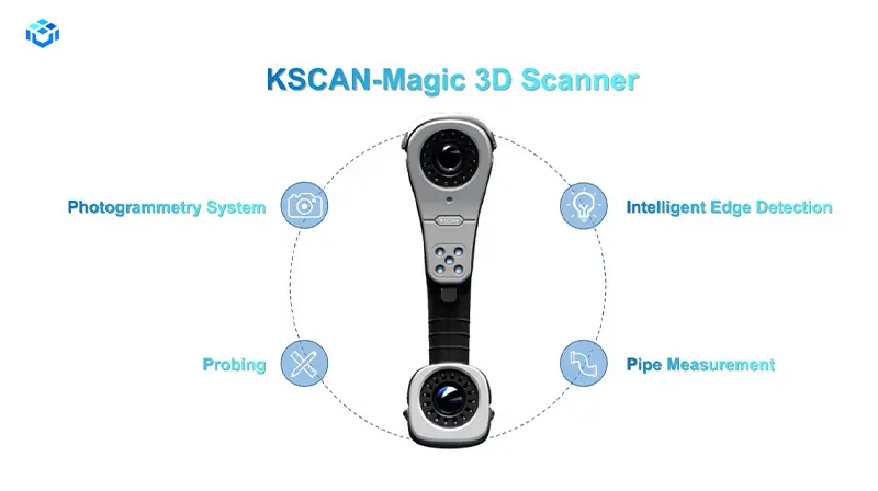
To address limitations with reflective surfaces encountered using red-laser scanners, Fabspeed upgraded to the SCANTECH KSCAN-Magic handheld 3D laser scanner. This blue-laser technology offers enhanced accuracy (up to 0.020 mm) and resolution (up to 0.010 mm), scanning at a rate of 4,150,000 measurements per second without the need for sprays or excessive markers.
A notable application involved scanning a Porsche 911 Carrera 4 GTS to replace a discontinued muffler. The KSCAN-Magic enabled engineers to capture the necessary geometry and identify a suitable design within an hour, demonstrating the scanner's efficiency and precision.
By embracing advanced 3D scanning, Fabspeed has significantly improved its R&D cycles, production timelines, and overall competitiveness in delivering custom automotive solutions.
Revolutionizing Jewelry Design: How Cooksongold Leverages Artec Micro for Rapid, High-Precision 3D Modeling
Revolutionizing Jewelry Design: How Cooksongold Leverages Artec Micro for Rapid, High-Precision 3D Modeling
In the world of jewelry design, precision and efficiency are paramount.Cooksongold, a leading UK-based supplier of precious metals and components, has embraced cutting-edge technology to enhance its design and manufacturing processes.By integrating the Artec Micro 3D scanner into their workflow, Cooksongold has significantly reduced the time required to create detailed 3D models of intricate jewelry pieces.
The Challenge: Capturing Fine Details of Reflective Jewelry
Jewelry items, often crafted from reflective metals and adorned with gemstones, present unique challenges for 3D scanning.Traditional methods can struggle to capture the fine details and intricate features of such pieces.Recognizing this, Cooksongold sought a solution that could accurately digitize these complex designs
The Solution: Artec Micro 3D Scanner
The Artec Micro, known for its high-resolution capabilities and precision, proved to be the ideal tool for the job.With its 5-micron accuracy, the Artec Micro captures even the most delicate features of jewelry pieces, including engravings and intricate textures.This level of detail is crucial for creating accurate 3D models suitable for redesign, preservation, or reproduction.
Streamlining the Workflow
Cooksongold's integration of the Artec Micro into their workflow has streamlined the process of creating 3D models.Previously, manually modeling intricate jewelry designs could be time-consuming and labor-intensive.With the Artec Micro, this process has been expedited, allowing for rapid digitization of pieces in just 1-2 hours—half the time it would take to model them from scratch.This efficiency not only accelerates the design process but also enhances the ability to iterate and refine designs quickly.
Applications and Benefits
The adoption of 3D scanning technology has opened new avenues for Cooksongold
Customization: Clients can now easily customize existing jewelry pieces by digitizing them and making modifications to suit personal preferences.
Restoration: Damaged or worn-out pieces can be accurately scanned and reproduced, preserving their original design and sentimental value.
Prototyping: Rapid prototyping becomes feasible, allowing designers to test and refine concepts before committing to full-scale production.
Preservation: Heirloom pieces can be digitized and stored, ensuring their details are preserved for future generations.
Looking Ahead
As the jewelry industry continues to embrace digital technologies, the role of 3D scanning in design and manufacturing is set to expand.Cooksongold's successful integration of the Artec Micro serves as a model for other companies looking to enhance their processes.By leveraging advanced tools like the Artec Micro, businesses can achieve greater precision, efficiency, and creativity in their designs.
For more information on how Artec 3D scanning solutions can transform your jewelry design process, contact us at info@rapidscan3d.com
Main article https://www.artec3d.com/cases/cooksongold-jewelry
How Eva Cast and 3D Scanning Are Revolutionizing a Leading Foundry’s Workflowning for pipeline integrity management
How Eva Cast and 3D Scanning Are Revolutionizing a Leading Foundry’s Workflow
In the world of traditional foundries, precision and efficiency are key to producing high-quality metal castings. But as manufacturing evolves, so too must the technologies that support it. That’s where Eva Cast, powered by cutting-edge 3D scanning technology, steps in — transforming how one leading foundry operates and sets new standards in their industry.
The Challenge: Precision and Speed in Metal Casting
Foundries face numerous challenges, including tight production timelines, the need for precise mold designs, and reducing costly errors. Conventional methods often rely on manual measurements and trial-and-error adjustments, which can slow down production and impact product quality.
Enter Eva Cast and Artec 3D Scanning
Eva Cast, equipped with Artec 3D scanners, brings a modern solution to these traditional problems. By integrating 3D scanning into the foundry’s workflow, Eva Cast enables rapid, highly accurate digitization of molds, prototypes, and casting patterns.
The Artec 3D scanners’ ability to capture fine surface details without contact ensures that delicate mold components are preserved during inspection. This precision allows the foundry’s engineers to detect deviations early and adjust their processes accordingly — saving time and reducing waste.
Key Benefits Realized
Faster Iterations: The foundry can quickly scan and analyze casting patterns, accelerating design modifications and mold corrections.
Improved Accuracy: High-resolution 3D models reveal imperfections that might go unnoticed with traditional inspection, leading to better final products.
Cost Savings: Reducing rework and scrap results in significant cost reductions over time.
Streamlined Collaboration: Digital 3D models facilitate easier communication between design, engineering, and production teams.
Real-World Impact
Thanks to Eva Cast and Artec’s innovative 3D scanning technology, this foundry has dramatically improved its production workflow. The newfound speed and precision not only enhance product quality but also strengthen the company’s competitive edge in the marketplace.
Why 3D Scanning Is a Game-Changer for Foundries
Eva Cast’s success story illustrates a broader trend: the growing adoption of 3D scanning technology in manufacturing sectors traditionally reliant on manual processes. By embracing this digital transformation, foundries can:
Reduce lead times from design to production,
Ensure consistent quality and repeatability,
And unlock new levels of efficiency and innovation.
Ready to see how 3D scanning can elevate your foundry or manufacturing process? Discover more about Eva Cast’s starring role and explore how Artec 3D solutions can help you achieve breakthrough results.
Scaling new heights with Artec 3D scanning: Inspecting a 25-foot tall floodwall
Challenge:Accurately capturing part of a 3.28-mile floodwall under an active overpass. So busy it vibrates with the movement of passing cars, the GoMeasure3D team sought to identify a quantifiable way of inspecting the massive structure for damage.
Solution:Artec Leo, Artec Ray II, Artec Studio, SOLIDWORKS, Geomagic Design X, Geomagic Control X
Result:A highly detailed digitization, ideal for uncovering deformations, measuring corrosion, and assessing the wall’s maintenance needs. Thanks to Artec Studio software, going from scan to inspection-ready mesh – a process that traditionally takes two days – took just 90 minutes.
Why Artec 3D?:Artec Ray II’s built-in display and GPS tracking make large-scale capture challenges routine tasks. To inspect areas with finer details, it’s also possible to follow up with 0.1mm-accuracy Leo scans and combine multiple datasets into hyper-realistic 3D visualizations.
The University of Cambridge's cutting-edge research into ancient ceramics has been transformed by the use of the Artec Space Spider, a highly accurate 3D scanner. This technology enables researchers to create detailed digital models of artifacts, revealing nuances in shape, curvature, and wall thickness that were previously undetectable. These insights shed light on the manufacturing techniques and social dynamics of stateless societies, offering a deeper understanding of ancient collaboration and innovation.
Partnering with Artec 3D experts, the research team utilized the scanner for non-invasive studies of historical objects, including bowls, spindle whorls, and stone carvings. The precision of up to 0.05 mm allowed researchers to document over 100 artifacts and further analyze them using specialized software. This breakthrough is not only advancing archaeology but also demonstrating how technology can preserve and reinterpret history for academic and public engagement.
For a demo or information please contact us at info@rapidscan3d.com or (562) 912-3544
Phoenix reborn: Artec Leo helps preserve Drago di Vaia, the world's largest wooden dragon
Italian artist Marco Martalar rebuilt his iconic "Drago di Vaia" sculpture using six tons of storm-damaged wood after it was destroyed by arson. To preserve this majestic work, UnoArte utilized Artec Leo scanners to create a highly detailed 3D digital twin. This innovative scanning captured every intricate detail of the 16-meter-long wooden dragon, enabling its legacy to live on digitally. The project highlights the role of technology in safeguarding cultural heritage.
For a demo of the Artec Leo - Contact info@rapidscan3d.com or (562) 912-3544 Learn more: Artec 3D.
Why 3D Vision Will Gradually Replace 2D Recognition Technology
3D vision technology is gradually replacing 2D systems by offering greater precision, depth, and adaptability. Unlike 2D vision, which captures only X and Y data, 3D systems use advanced sensors to generate accurate spatial models, making them ideal for complex manufacturing and inspection tasks. 3D vision overcomes limitations of 2D technology, such as sensitivity to lighting and difficulty with 3D shapes, enabling applications in robotics, quality control, and assembly.
“It’s the largest object we ever scanned!” Artec 3D scans gigantic gas engine in Luxembourg
Artec 3D scanned a massive 19th-century gas engine in Luxembourg, marking one of the largest scanning projects they've undertaken. The engine, too large to move, was scanned on-site using Artec’s powerful, portable scanners. This complex process captured precise details for digital preservation and future restoration needs, creating a highly detailed 3D model of the engine. This case illustrates how advanced 3D scanning technology can preserve industrial heritage by digitizing even the largest and most intricate objects.
Gas Engine #11
Built in 1938 by Ehrhardt & Sehmer, the Groussgasmaschinn is the largest gas engine ever built
Built in 1938 by German manufacturing company Ehrhardt & Sehmer by order of a Franco-Belgian consortium called “Hauts-fourneaux et Aciéries de Differdange, St-Ingbert & Rumelange” (HADIR), the Groussgasmaschinn is so large it could contain an entire tennis court, and then some. It is 26 meters long, 10.5 meters wide, and 6.5 meters high, weighs 1,100 tons, and was able to produce 11,000 horsepower, or up to 7000 kilowatts. It has four cylinders, each of which had a capacity of 3,000 liters, and an 11-meter and 150-ton flywheel, which rotated at 94 RPM. The engine was operated by 12 workers per shift, and during its lifetime (1942-1979) produced more than 6,000 kW of power from blast furnace gas (a waste product generated by the combustion of coke fuel in blast furnaces).
As in most cases, the size and complexity of the object determines the scanners to be used. Artec Ray was chosen as the primary scanner for capturing the entire engine, due to its ability to scan large objects from a distance with submillimeter accuracy, while the Artec Leo, a wireless, portable 3D scanner, was chosen as a second device, specifically for capturing high levels of detail from the smaller parts and sections of the engine.
While Ray silently scans the engine, Zaremba steps away for a minute or two of scanning smaller sections up close with Leo
The final polygonal 3D model of the Groussgasmaschinn
From 1940s all the way to 2020s, the Groussgasmaschinn got a second breath thanks to the power of 3D scanning technologies
Challenge:To compare the accuracy of a portable 3D scanner versus photogrammetry for documenting forensic footwear impressions in soil and sand, while exploring 3D scanning as a replacement for the traditional method of casting footwear impressions at crime scenes.
Solution:Artec Space Spider, Artec Studio
Result:In less than one minute, footwear impressions can be documented in 3D at crime scenes using the Artec Space Spider, with a level of accuracy superior to photogrammetry. Unlike footwear impression castings, these 3D “digital castings” are unbreakable, easy to transport and store, and can be depended upon for many years to come.
Why Artec 3D?Now, footwear impressions can be documented in submillimeter-precise color 3D, without having to resort to messy, complicated, and lengthy (24-48 hours to dry) casting protocols. The Space Spider makes it easy for non-specialists to capture footwear impressions, and then share the scans with their respective forensics teams while still on scene.
Other than DNA, two common types of evidence that can link a specific person to a crime scene are fingerprints and footwear impressions. With all the popularity of TV crime shows and CSI documentaries, many criminals have become smarter, wearing masks to hide their faces, and using gloves to avoid leaving fingerprints.
Yet it’s extremely rare for any criminal to cover or even attempt to modify their footwear. This is why practically every crime scene is filled with footwear evidence that can directly tie a suspect back to the crime.
If documented and collected properly, such evidence can offer up a wealth of details beyond suspect identification, even making it possible to reconstruct part of the crime itself: the type, brand, size, and specific model of shoe, the number of suspects at the scene, their paths moving to, through, and away from the area, and possibly even the sequence of events that took place.
From collection to comparison
After a footwear impression has been collected, either full or partial, it can be compared to thousands of reference shoes via searchable databases such as SICAR, the National Footwear Reference Collection (NFRC), EverASM, and SoleMate FPX.
By finding a match, investigators will see all the class characteristics of the footwear, which are those produced during manufacturing, such as any logos, designs, the tread pattern, etc.
On the other hand, what’s known as “individual” or “randomly acquired” characteristics of the shoe won’t be found in any of the above databases, since they’re purely the result of ongoing wear patterns together with accidental changes. These features set each shoe apart from all others.
They can include scratches, nicks, cuts, holes, abrasions, tiny pebbles, or other material wedged between treads, etc. What makes these combinations of characteristics so critical for linking a specific shoe to an impression found at a crime scene is the astronomically small chance of another shoe having one or more of the same randomly acquired characteristics in the same locations.
Forensic footwear specialist comparing photo of impression with shoe
According to the FBI, the surface area of a size 8.5 shoe’s outsole is approximately 16,000 square millimeters. So, if there’s even one random characteristic present that’s just 1mm in size, whether that’s a cut, a pebble, or a scratch, the chance of this showing up on another shoe in that same location is a mere one in 16,000.
That’s not even taking into consideration the shoe size and the sole design, as well as the orientation, shape, or size of the characteristic.
Now, if we bump that up to two or three accidental characteristics in the same respective locations on two separate shoes, the chances plummet dramatically: for two, it’s one in 127,992,000, and for three, it’s a microscopic one-in-683-billion chance.
Linking an impression to a shoe and to a suspect
To see how these impressions are used in an actual crime investigation, let’s say that a footwear examiner, using a searchable database, determines that a murder suspect was wearing a pair of size 15 Nike Air Jordan XXXVIs.
The examiner can narrow down their search to finding the wearer of that shoe, but an identification will only be made once they can link the footwear impression made at the scene to the actual shoe via the corresponding individual characteristics, the so-called “fingerprint” of the shoe.
Unfortunately, as crucial as they can be to an investigation, footwear impressions are some of the most fragile pieces of evidence found at or around a crime scene. So, they need to be documented and collected immediately, especially if they’re outside and vulnerable to the elements of nature, not to mention the risk of contamination by first responders and passersby.
Forensic photography & casting: traditional documentation and collection methods
Over the years, the procedure for documenting footwear impressions by taking examination-quality color photographs has evolved to where it is today: the camera must be carefully positioned on a tripod with the film plane parallel to the impression, so that every photograph includes a rigid scale on the same plane as the bottom of the impression.
During the collection stage, 2D footwear impressions (latent or patent), made on hard, flat surfaces, have called for either electrostatic, adhesive, or gelatin lifting.
2D footwear impressions ready for forensic documentation
Whereas 3D impressions, made in softer, uneven substrates such as sand or soil, because of their depth characteristics, have required either silicone- or gypsum-based casting solutions such as dental stone, which has been the material of choice for decades now.
The struggles of casting footwear impression evidence
A serious drawback of the casting method is that it’s a contact-intensive, destructive process, which means there’s only one chance before the original impression has been damaged and is no longer useful as evidence.
As soon as the casting material has been mixed and ready, it must be uniformly poured into the footwear impression at just the right speed. Otherwise, the downward impact of the material can easily ruin the cast even before it’s had a chance to harden. This process is greatly dependent on the skill of the crime scene technician.
Other issues may arise with incorrect mixing ratios or when bubbles exist in the mixing material, which can render the cast useless from an investigative perspective, since this is likely to bring about gaps in the final, hardened cast.
Another challenge with this approach is that the casting material often picks up rocks, stones, dirt, grass, twigs, and other bits of debris, so they become part of the cast. Yet before such materials can be picked out of the casts, the casting material first needs to completely harden, otherwise the casts can be seriously damaged.
3D footwear impression cast (dental stone) at a scene
While still at the scene, the cast will take 45 minutes to an hour to set. Only then can it be transported away and safely stored for the 24-48 hours it takes to fully harden, and then cleaned of debris, as required.
If the need arises to collect 3D footwear impressions in snow, a different route is called for. Since while a gypsum-based cast is drying, it’s also releasing heat, enough to melt the snow.
To prevent this, a product such as Snow Print Wax® can be sprayed onto the snow footwear impression, while being careful not to spray too closely or apply too much, as these may distort the original impression pattern. Once the spray has dried, the casting material can be carefully poured into the impression.
Forensic footwear impression in snow
Only when the casts are fully dry should they be handled and used for the investigation. Since they’ll need to be stored as evidence, both before the trial and perhaps indefinitely, their hefty size and weight will need to be taken into account, particularly since they’re also prone to breakage if dropped or mishandled.
3D scanning for fast & easy, non-destructive evidence collection
More than a century ago, when the father of forensic science, Edmond Locard, announced to the world that “Every Contact Leaves a Trace,” perhaps he was also referring to evidence collection methods and how they, without exception, would at least alter if not outright destroy the evidence itself.
Today, more and more law enforcement agencies and investigators are using3D scanners for documenting and collecting evidence, including footwear impressions. 3D scanners are by nature, non-contact, and non-destructive, making them an ideal choice for the task at hand, as scanning can be done easily and safely, without any risk of damage to the evidence.
Unlike the hours of waiting needed before footwear impression casts are dry, the resulting 3D models from scanners can be ready just minutes after capturing, even out at the crime scene. They can be shared with other investigators, technicians, and agencies, across the city, the state, or beyond.
Some 3D scanners can also be used to capture footwear impressions in snow, as evidenced by the following two screenshots made after a 1-minute Artec Leo scan of boot prints in snow, in England, courtesy of Artec Gold Certified partnerPatrick Thorn.
Artec Studio screenshot showing Leo scans of footwear impressions in snow. Photo: Patrick Thorn
As explained previously, even with special sprays to protect the snow from damage during the casting process, many forensics teams either don’t have on-scene access to these tools, or simply don’t have the time and resources available to wait for the 24-to-48-hour casting process to conclude.
Artec Studio screenshot showing Leo scans (texture removed) of footwear impressions in snow. Photo: Patrick Thorn
Weighing the evidence: 3D scanning vs. photogrammetry & casting
Recently a forensics research study was carried out in order to understand whether 3D scanning solutions can be a suitable replacement for casting footwear impression evidence, as well as to see how well it compares to modern digital photogrammetry.
The study,Recovery of Footwear Impression Evidence Using Portable 3D Scanning Technologies, was carried out by Ontario Tech University forensic science researcher and student Julia Harvey as part of her FEPAC Accredited Forensic Science undergraduate degree program’sBachelor’sHonors Research Thesis.
Harvey accomplished the objectives of her research in collaboration with Eugene Liscio, P.Eng. ofai2-3D Forensics; Theresa Stotesbury PhD, Ontario Tech University; and local police agencies. Central to the study was theArtec Space Spider, a professional handheld 3D scanner that’s been a favorite in forensics, paleontology, medicine, and other fields for years, together withArtec Studiosoftware.
Forensic science researcher Julia Harvey using the Artec Space Spider to document a 3D footwear impression. Photo: Eugene Liscio, P.Eng., ai2-3D Forensics
The Space Spider captures up to one million data points per second, with an accuracy of 0.05 mm (the width of a human hair), giving users the power to scan even the most complex of footwear impressions in under one minute, with no targets or markers required.
Carrying out the study, step by step
At the heart of the workflow, Harvey created four separate footwear impressions (using a boot and a sneaker) in two different substrates (soil & sand), and performed distance computations in CloudCompare to determine the accuracy of the resulting 3D models from the Space Spider scans versus the 3D models made using photogrammetry. For capturing the impressions via photogrammetry, a Nikon 24.1 MP D7100 DSLR was used.
Watching the 3D evidence come to life: forensic science researcher Julia Harvey documenting a 3D footwear impression with the Artec Space Spider. Photo: Eugene Liscio, P.Eng., ai2-3D Forensics
The results of the study include the following: distance computations between the Artec Space Spider point clouds and high-resolution baseline 3D models made via a tripod-mounted 3D scanner showed that 97% of points had an absolute distance of 0.492 mm or less. The same computations for photogrammetry and the baseline 3D models resulted in 97% of points having an absolute distance of 0.512 mm or less.
Heatmap comparison showing the superior accuracy of Space Spider (top) versus photogrammetry (bottom) for documenting 3D footwear impressions. Photo: Eugene Liscio, P.Eng., ai2-3D Forensics
“As the results of our study show, with the Artec Space Spider, when it comes to collecting footwear impression evidence at crime scenes, it’s possible for a portable 3D scanner to replace casting. The results are similar to 2D photography, with the added benefit of being able to view all of an impression’s details up close, from every possible angle,” said Harvey.
Not that just any 3D scanner will suffice. Typically,professional 3D scannershave much higher accuracy and lower noise levels than cheaper solutions. Harvey’s research shows that if too much noise is present in a scan, the impression must be rescanned, and this can multiply the time needed for recovery.
Artec Studio screenshot showing Space Spider scan of a boot impression. Photo: Eugene Liscio, P.Eng., ai2-3D Forensics
Additionally, impressions made in various substrates, such as wet soil, mud, etc., can be challenging for many 3D scanners to capture, due to excessive reflectivity and other issues, so these scenarios should be tested prior to actual crime scene usage, to confirm that the chosen device is able to capture the entire impression, including all the crucial small-class and individual characteristics.
Artec Studio screenshot showing Space Spider scan (texture removed) of a boot impression. Photo: Eugene Liscio, P.Eng., ai2-3D Forensics
Aside from the accuracy of 3D scanning versus photogrammetry, forensics specialists and agencies benefit from several other aspects, including the following:
the speed of capture (less than a minute per impression);
the ability to do analyses while still at the scene (distance calculations between outsole features and individual characteristics);
easily storing and sharing 3D data between departments and agencies;
the ability to 3D-print lifelike replicas for court or investigative purposes.
3D-printed scale models of forensic footwear impressions, for demonstration purposes. Photo: Eugene Liscio, P.Eng., ai2-3D Forensics
Harvey would like to see future directions of research to include the 3D collection of incomplete footwear impressions, along with impressions made in different substrates, or in different weather conditions. 3D comparisons of known footwear to unknown impressions could also be useful for law enforcement agencies.
“Beyond capturing footwear impressions at crime scenes, professional 3D scanners can do so much more, from documenting bloodstain patterns, bullet holes, human bodies and remains, as well as weapons, tools, and other objects, including the entire scene around. I believe we’re just seeing the beginning of what 3D scanning can do in forensics and elsewhere,” said Harvey.
3D Inspect Cast Gearbox Housing For Machining Allowance Analysis
The manufacturing of complex and large-scale alloy die castings is essential in various industries, including automotive, telecommunications, renewable energy, aerospace, and electronics. As demand for precision in these sectors increases, the necessity for advanced manufacturing techniques and strict quality control intensifies.
Introduction of the Client
The client specializes in the manufacturing and processing of large, complex alloy die castings. It boasts an annual production capacity of 30,000 tons. Their advanced equipment and sophisticated management and processing techniques have established them as a key player in various high-tech and industrial sectors.
Cast Gearbox Housing To Be Measured
The casting gearbox housing is designed to enclose and support the gears and bearings, which is crucial for transmission systems to function properly. A well-designed gearbox housing should be able to withstand the loads and stresses it experience during operation.
Measurement Challenges
Castings often have intricate geometries and features that can be challenging to measure. These include internal cavities, ribs as well as curved surfaces, fillets, chamfers, and non-planar faces with irregular shapes. Accurate measurement of these intricate details is crucial for quality control and ensuring proper fit and function.
Limits of Previous Measurement Methods
Traditional measurement techniques struggle to capture complete and accurate data due to the complexity and depth of these parts. The conventional methods fall short in several areas:
Limited Access:Deep cavities and tight corners are difficult for traditional measurement methods to reach.
Incomplete Data:Traditional methods can only measure certain key points, missing out on the full surface data required for thorough analysis.
Cumbersome Defect Identification:Identifying and quantifying defects in these intricate parts is a cumbersome process with traditional techniques.
Scantech's 3D Solutions
To address these challenges, the company used Scantech’ssmart handheld 3D scanner SIMSCAN. It is designed to handle the measurement challenges of narrow spaces, making it ideal for measuring this deep-cavity casting. The SIMSCAN offers a compact and versatile toolset that significantlyenhances the inspection process.
Inspection Process
3D Laser Scanning:Utilizing the SIMSCAN, a point cloud of the part was generated in just five minutes.
3D Modeling:This point cloud data was transformed into a model.
Data Analysis:Specialized software compared the actual model with theoretical model, producing a detailed color map that highlights machining allowances.
Key Measurements and Inspections
Allowance for Machining:Ensured there was sufficient material to allow for machining without compromising the integrity of the part.
Overall Dimensions:Measured the length, width, and height of the housing to ensure it meets the design specifications.
Bore Diameters:Measured the diameters of holes, especially those for shafts and bearings, to ensure they were within tolerance.
Surface Flatness:Assessed the flatness of surfaces that would be machined to ensure they were within acceptable limits.
Advantages of the SIMSCAN
The compact size of SIMSCAN enabled convenient access to deep cavities. Its 130-mm short camera distance enabled a steeper view angle, allowing effective laser scanning even in shadowed areas and tight corners with an accuracy of up to 0.020 mm. Additionally, the scanning process was highly efficient, providing comprehensive data at a rate of 2.8 million measurements/s, much faster than traditional methods. Most importantly, it ensured accurate measurements of complex surfaces, meeting necessary standards.
Benefits of 3D Solutions for Determining Machining Allowance
Comprehensive Data:3D laser scanner SIMSCAN captured the complete geometry of the gearbox housing, including complex surfaces and hard-to-reach areas. This comprehensive data collection ensured that no features are overlooked and provides a complete picture of the part's condition.
Precision and Accuracy:3D scanning technology provided extremely precise and accurate measurements. This was critical for determining the exact machining allowance needed for a gearbox housing, ensuring that the finished product meets all specifications and quality standards.
Efficiency:Traditional measurement methods can be time-consuming, involving manual measurements and potentially multiple iterations. SIMSCAN 3D scanning significantly reduced the time required to gather detailed dimensional data, speeding up the entire inspection and machining process.
Digital Archiving:3D scanning created a digital record of the gearbox housing's condition at various stages of the manufacturing process. This digital archive can be used for future reference, quality control, and to ensure traceability in production.
Baseline Establishment:Facilitated the quick and accurate determination of machining baselines, optimizing machining processes and reducing setup times.
Conclusion
The application of Scantech's SIMSCAN in gearbox housing inspection marks a significant advancement for the company. This innovative 3D solution not only overcomes the limitations of traditional measurement methods but also provides a more efficient, accurate, and cost-effective approach to identify machining allowance and enhance quality control. As industries continue to evolve, the adoption of such cutting-edge technologies will be crucial in maintaining competitive advantages and ensuring the highest standards of precision and reliability.
3D Digital Solutions for Automotive Mold and Die Inspection
The production of automotive parts relies heavily on molds and dies, which must be manufactured to exact specifications to ensure the integrity and performance of the final product.
The process of developing molds and dies for major body panels involves several critical steps. These include die design, pattern development, casting, construction, and tryout. Among these, the construction phase stands out as the most costly and time-consuming.
Traditional inspection methods, while effective to an extent, often fall short in capturing the minute details and complex geometries of these tools. This is where 3D scanning can help toenhance the inspection process. By employing high-precision 3D scanning for automotive mold and die inspection, manufacturers can achieve high accuracy, efficiency, and reliability.
This article shed lights on how 3D scanning can help to improve automotive die inspection, exploring how it enhances quality control, reduces downtime, and drives innovation in the automotive manufacturing sector.
Challenges of Measuring Molds and Dies
Size and Mobility:Automotive molds and dies are large, therefore, it is hard to transport them to dedicated measurement rooms.
Complex Geometries:Molds feature intricate surfaces with undercuts, sharp edges, deep cavities, and fine details. Traditional methods struggle to capture such complexity accurately.
Reflective Surfaces:The measurement of metallic molds may result in measurement noise due to their reflective nature.
Significance of Measuring Molds and Dies
Thorough inspection is essential to ensure that the molds and dies align with the original design. Errors resulting from machining not only affect the die assembly but also impact the die’s ability to create acceptable panels during tryout. If any dimensional errors are detected during assembly or tryout, it can significantly delay the delivery of the complete die to production by several days or even weeks.
When an error is identified, construction is halted, and an extensive root cause analysis begins. To prevent delays caused by process errors, precise inspection of die is crucial.
Measure a Die to Assess Dimensions, Flatness and Defects
For this project, our client needed to inspect a die used in the production of automotive stamping parts. The goal was to assess geometric dimensions, flatness, and identify any defects.
Challenges
Due to the die’s large size and weight, it is inconvenient to move it. It is necessary to measure it right on the shop floor.
The die has intricate features, including curved surfaces, holes, concave-convex areas, and sharp corners. Moreover, there are obstructions and blind spots that conventional measuring tools struggle to handle.
Additionally, the reflective surface of the mold could potentially interfere with 3D laser scanning, affecting measurement accuracy and precision. It’s worth noting that the customer has specified no powder coating or target sticking.
3D Scanner: TrackScan-Sharp
TrackScan-Sharp optical 3D measurement systemwas used to capture the physical geometry of the molds. It brings optical measurement to a whole new level by offering a tracking distance of up to 6 meters, a volumetric range of 49 m3, and volumetric accuracy of up to 0.049 mm (10.4 m3).
Workflow
Laser Scanning:The 3D scanner captured the mold’s surface, creating a point cloud representation on a computer.
Data Generation:Import the scanned point cloud data into computer software for processing. Next, perform alignment, registration, and other necessary operations to convert it into STL data.
Deviation Analysis:By comparing the scanned data with the original CAD model, we identified any deviations from the design specifications. This analysis guided subsequent steps.
Benefits
On-Site Measurement Process:The entire measurement process occurred on-site within the workshop, as TrackScan-Sharp is portable and resistant to vibrations.
Powder-Free and Target-less Measurement:Thanks to its optical tracking and advanced algorithm, TrackScan-Sharp eliminated the need for powder spraying or attaching targets to the objects being measured.
Efficient Workflow:Leveraging its impressive 49-m3 measurement volume and high measurement rate, the 3D scanner ensured an efficient process. From initial scanning to the final inspection report generation, the entire cycle was completed in a remarkably short time—just 40 minutes.
Inspection of Large-scale Molds
Project Objective
The primary objective of this project is to perform a comprehensive inspection of car roof die using the advancedKSCAN-Magic 3D laser scanner. The aim is to detect any deviations or defects, and improve the overall manufacturing process efficiency.
Challenge of Inspection Large-scale Die
Size and Complexity:The die features a large size and intricate details that are difficult to measure with traditional tools.
Precision Requirements:Automotive parts require high precision to ensure proper fit and function, necessitating highly accurate measurement tools.
Data Management:The vast amount of data generated during inspection needs to be processed and analyzed efficiently to provide actionable insights.
3D Scanner: KSCAN-Magic
TheKSCAN-Magic 3D scannerexcels in capturing detailed 3D data with high accuracy of up to 0.020 mm. It is highly versatile, suitable for scanning objects of various sizes and materials. With its high scanning speed, it enables quick data collection, while its user-friendly interface and portability make it suitable for use in various environments.
Workflow
Data Collection:Scan the entire surface of the car roof die, capturing detailed 3D data. The scanner's high precision and speed allow for quick and accurate data collection, even for large and complex dies.
Data Processing:Use the accompanying software to process the 3D data. The software aligns and merges the scanned data into a complete 3D model.
Analysis:Compare the scanned 3D data with the original CAD design to identify any deviations or defects. The software provides detailed reports on dimensional accuracy, surface quality, and other critical parameters.
Benefits
Ease of Use:The user-friendly nature of the KSCAN-Magic allows operators to quickly learn and efficiently perform inspections.
Efficiency:The fast scanning speed of up to reduces inspection times, helping to maintain production schedules.
High Accuracy:The high precision of the KSCAN-Magic ensures accurate inspection of even the smallest defects or deviations with an accuracy of up to 0.020 mm. KSCAN-Magic featured a built-in photogrammetry system, enhancing the accuracy and stability of measurements. This minimized errors and rework due to scan misalignment.
Flexible Operation:The 3D scanner scanned the die from various angles and distances, unaffected by workshop vibrations. It was also portable and lightweight, making it easy to carry on business trips.
Real-time Reporting:The professional scanning software generated color maps showing deviations by comparing the 3D data with the original CAD model.
Scantech 3D https://www.linkedin.com/pulse/3d-digital-solutions-automotive-mold-die-inspection-3dscantech-vnmxc/
Conclusion
The implementation of 3D scanning technology for mold and die inspection in automotive manufacturing significantly enhances production efficiency, quality control, and cost savings. By utilizing advanced 3D scanners like TrackScan-Sharp and KSCAN-Magic, companies can achieve precise, real-time, and comprehensive inspection results, ensuring that their molds and dies meet the highest standards of quality and precision.
Expanded Artec 3D Education Packages to improve 3D scanning training for students X Facebook Linkedin Email
Expanded Artec 3D Education Packages to improve 3D scanning training for students
3D scanning hardware and software leader Artec 3D has doubled down on its commitment to training the next generation by revamping itsEducation Packageoffering.
These bundles, which offer discounted access to an Artec 3D device and 20 Artec Studio software licenses – all you need to bring 3D scanning into the classroom – have now been expanded further.
From now on, educators who buy such a bundle will get two years’Artec Carecover, so they can teach freely with devices, knowing that they’re protected against accidental damage. Access to dedicated courses onArtec Academy, a virtual learning space packed with content developed by 3D scanning experts, has also been added to the promotional scheme.
Designed specifically for schools and universities, these EDU courses cover Artec Leo, Artec Eva, Artec Space Spider, and Artec Ray II data capture, as well as maximizing results on Artec Studio. Available to education package users* free of charge, the content will allow students to truly get the most out of each device, and hone skills with real-world applications.
Whether it be through expert tutorials, project support, product discounts, or behind-the-scenes tours of its facilities, Artec 3D has always made education one of its highest priorities.
During a recent Engineering Trainee Days initiative, for example, students were trained in-house by specialists. Elsewhere, on an exclusive factory tour, budding engineers were guided around Artec 3D’s production facility, where they got a hands-on Artec Leo & Artec Ray II tutorial.
Following this factory visit, Lycée de garçons de Luxembourg teacher Sabine Bouzette was blown away by the “truly exceptional” attitude of the Artec 3D team to encouraging students.
“We were received beyond all our expectations,” said Bouzette. “We found the reception, the explanations, the presentations, the tests of scanners really incredible! Hats off to this company – which gives young adults the desire to embark on studies, allowing them to create new technologies – and presents their company with enthusiasm.”
With the launch of these new Education Packages, it’s anticipated that Artec 3D’s impact in the classroom and across the education space will soon grow even further. But students aren’t the only ones who can benefit from Artec Academy – it offers plenty of industry courses too.
Artec Academy courses cover the complete 3D scanning workflow, challenge users to actively learn, and offer live training from Artec’s very best. Whether brushing up on skills or starting anew, each course gives subscribers everything they need to capture with confidence.
As well as courses around Artec handheld 3D scanners, Artec Ray II, Artec Metrology Kit, and Artec Studio, Artec Academy features a forensic 3D scanning course for digitizing crime scene evidence. With many more industry courses on their way, the platform is fast growing into a vital resource for users seeking to maximize their return on investment in 3D scanning.
Work in academia and want to know more? Check out ourEducation Packagepage. Our new dedicated academic courses are also available now (alongside other training courses) via theArtec Academy catalog.
Interested in getting an Education Package or signing up for an Artec Academy course? Contact us at sales@artec3d.com and we’ll connect you with your nearest reseller.
*Free access to EDU-marked Artec Academy courses will be granted to any Education Package user who has acquired their bundle since 2023.
Advancing Automotive Parts Manufacturing and Repair with 3D Scanning
The automotive industry is constantly evolving, driven by technological advancements and consumer demands. As vehicles become increasingly complex, the need for detailed and accurate measurements of automotive parts has intensified.
3D scanning technology has emerged as a crucial tool, offering precise and comprehensive data that supports the production and maintenance of automotive parts.High-tech 3D scanninghelps aftermarket parts manufacturers and repair shops to meet rigorous standards and expectations by ensuring precision and quality.
This article explores how a 3D scanning service provider uses Scantech's state-of-the-art SIMSCAN 3D scanning solution to adeptly tackle the measurement challenges in this sector.
3D Scanning Service Provider
Our client is a leading 3D scanning service provider specializing in 3D scanning, reverse engineering, and mechanical design. Their expertise lies in capturing intricate details of various objects and converting them into accurate digital models. Recently, they were tasked with scanning and 3D modelling 30 automotive spare parts for an electric vehicle known for its innovative design and engineering.
Automotive Spare Parts to be Inspected
The automotive spare parts range from exterior body panels to intricate interior components. Each part required a detailed and accurate scan to ensure that the digital models could be used effectively for 3D modelling and further processes. The exterior parts often have complex geometries and reflective surfaces, while the interior components are typically come in intricate details. The diversity in size, shape, and material of these parts added complexity to the scanning process.
Measurement Challenges
3D scanning automotive parts presents several challenges. Complex geometries, reflective and dark surfaces, and limited access in tight spaces complicate data capture. Large surfaces require consistent accuracy, and high precision is essential. Speed is crucial for industrial efficiency, and integrating multiple scans accurately is challenging.
Another significant challenge was the need to complete the scanning process within a tight timeframe. The client required the scanning of all 30 parts to be completed within 120 minutes. This necessitated a scanning solution that could deliver high-speed performance without compromising on the quality and accuracy of the data.
Limits of Previous Measurement Methods
Traditional measurement methods, such as calipers, gauges, and coordinate measuring machines (CMM), have several limitations. These methods are often time-consuming, require manual intervention, and may not capture the full 3D data of intricate parts. These limitations necessitate the adoption of advanced 3D scanning technologies that can overcome these challenges and deliver superior results.
Scantech's 3D Solutions
Scantech'ssmart handheld 3D scanner SIMSCANaddresses these issues with high-precision scanning, versatility on various surfaces, a compact design for confined spaces, and fast scanning speeds. Its non-contact measurement ensures delicate parts remain undamaged, and advanced software aids in precise alignment, overcoming environmental variables and enhancing manufacturing and repair.
High-Speed Scanning:The SIMSCAN can capture high-precision data at an impressive speed of 2.8 million measurements/s, allowing the scanning of all 30 parts within the required 120-minute timeframe. This efficiency is critical for meeting tight deadlines without sacrificing quality.
High accuracy:The advanced scanning capability and algorithms of the SIMSCAN ensured precise alignment and comprehensive data capture, enhancing the overall accuracy of the inspection process with an accuracy of up to 0.020 mm.
Detailed Interior Scanning:With its compact design and high precision, the SIMSCAN can access and scan interior components effectively, capturing every detail with high accuracy.
Adaptability to Various Surfaces:The SIMSCAN excels in scanning dark and reflective surfaces. This capability is particularly beneficial for automotive parts, which often have such challenging surface properties. By handling these surfaces with ease, the SIMSCAN saves significant time and effort, streamlining the entire inspection process.
Benefits of Scantech's 3D Solutions
The adoption of Scantech's SIMSCAN offered several benefits to the client:
Ensuring Fit:SIMSCAN ensures that new or replacement parts will fit correctly with existing components, thanks to its accurate scanning capabilities.
Reproducing Parts:The SIMSCAN's high-resolution scanning capabilities enable capturing intricate details of existing parts, facilitating the creation of precise digital models for reproducing parts that need to be replaced.
Maintenance Records:With SIMSCAN, maintaining accurate records of parts and their conditions over time is simplified, aiding in effective maintenance and repair operations.
Custom Modifications:The portable SIMSCAN allows for quick and precise scanning of existing parts, enabling the design of custom or modified parts that fit seamlessly.
Scantech's SIMSCAN 3D scanning solution proved to be a game-changer for the client, addressing all the significant challenges associated with scanning automotive spare parts. The high-speed and precise 3D scanning, and the ability to handle difficult surfaces and confined spaces resulted in a highly efficient and effective scanning process. The detailed and accurate 3D data obtained from the scans enabled the client to perform precise 3D modelling, ultimately contributing to the advancement of their services in the automotive industry. This case study underscores the transformative potential of cutting-edge 3D scanning technology in overcoming complex measurement challenges and enhancing operational efficiency.
Rapid Scan 3D is an authorized Scantech 3D reseller. If you are interested in a demonstration on hardware and software please contact.
E: info@rapidscan3d.com
P: (562) 912-3544
Original Article https://www.linkedin.com/pulse/advancing-automotive-parts-manufacturing-repair-3d-scanning-o9ogc/
Revolutionizing Wind Power Industry: Enhancing Stator Frame Processing with 3D Scanning Technology
As the global demand for clean, carbon-free electric power intensify, renewable energy sources such as wind power have experienced tremendous growth in adoption.
In the wind power industry, the stator frame plays a pivotal role as it secures and supports coils, ensuring their precise and stable positioning, which directly impacts the performance and operational capacity of wind power generators.
To guarantee the quality of the final product and the accuracy of precision machining,high-precision 3D laser scanners are increasingly used by customers to inspect blanks of stator frames.
Through this blog, we delve into how 3D scanning technology can revolutionize workflows in the wind power industry.
01 Customer Requirements:
In processing stator frames, locating the datum is paramount, as it directly influences the precision of the entire process.
Any deviation in the flatness, perpendicularity, or parallelism of the datum can lead to dimensional variations and positional shifts during subsequent processing, potentially causing part malfunctions.
The customer in this scenario seeks to obtain geometric dimensions of the stator frame blank surface to properly locate the datum. This ensures subsequent processing precision while minimizing errors.
Traditional method of locating the datum with a dialgauge can be inefficient and time-consuming. With 3 hours to locate a datum, only a few hundred pieces are output, which could not meet the expected production capacity requirements.
02 Project Challenges:
As the wind generator’s stator frame features with large size, a 3D scanner that has a large measurement volume, high resolution accuracy is necessary to capture precise 3D data of its key features.
The stator frame has a metallic reflective surface and hard-to-measure geometric features, such as curves and edges. These pose challenges for the complete collection of data by conventional measuring equipment.
03 Solution: TrackScan-Sharp
Fast Scanning:Leveraging theTrackScan-Sharp tracking 3D scanning systemenables rapid scanning of stator frames without the need for markers. This eliminates time spent on applying and removing markers, streamlining inspections in just five minutes.
Model Acquisition: With a maximum accuracy of 0.025mm, TrackScan-Sharp swiftly acquires high-precision 3D point cloud data. This data is imported into professional software to generate clear and intuitive 3D model of the stator iron frame.
Machining Allowance Analysis: The software facilitates comparison and analysis between 3D models and standard CAD models, confirming machining allowances on each processing surface of the blank. The intuitive report assists in locating the datum, providing guidance for subsequent machining processes.
04 Advantages of the Solution:
Ensuring Precise Processing: The 3D data acquired by TrackScan-Sharp guarantees more precise processing, allowing each step to be executed in the correct position and direction, thereby enhancing overall processing precision.
Improving Processing Efficiency: With a point cloud acquisition rate of 2.6 million measurements/second, the dimensions, shapes, and key data information of the blank can be quickly obtained, greatly shortening the processing cycle compared to traditional measurement methods.
Reducing Production Costs:Allowance analysis helps to determine the amount of material to be removed when machining the blank, thereby minimizing material waste, significantly reducing rework and scrap rates.
05 What Customer Says:
Scantech’s 3D scanner facilitated the acquisition of precise 3D data from the stator frame blanks, enabling us to accurately determine the datum and machining allowances.
This significantly enhanced the quality and efficiency of our machining processes, preemptively addressing potential issues and minimizing resource wastage due to deviations.
Committed to innovation, Scantech continually advances 3D scanning technology, injecting fresh momentum into digital transformation across industries.
Through our dedication to cutting-edge3Dsolutions, we strive to drive forward more sophisticated and sustainable technological advancements in industry development.
What once seemed impossible becomes reality with 3D scanning
Geomagic Customer Story
Marta Matvijev
When should you perform 3D scanning? As with other tech novelties, the unbridled enthusiasm for scanners makes it difficult to differentiate the hype from the valuable applications.
Should you decide to seek out the answer in the vast online wilderness, you’ll discover some interesting passion projects and creative feats of engineering. Scanning body parts and boats seems to be a particularly popular pastime!
Fun and games aside, the world of manufacture faces growing demands: short lead times, narrow tolerances, measuring complex shapes in extreme environments (think suspended bridges!). Under such circumstances, the value of 3D scanning is clear.
3D scanning for inspection
In particular, anyone conducting an inspection is likely to benefit from scanning due to the large amount of data that scanners can gather, the accuracy of the measurements and its non-contact nature. Two great examples of this come fromSCAN IT 3D, a 3D scanning service provider and Geomagic partner that is based in Germany and Switzerland.
SCAN IT 3D has worked on a range of scanning projects, from reverse engineering vintage car parts, scanning entire trains, to inspecting pipes and modelling heads... You name it, they’ve scanned it.
Out of this wealth of cases, we’re going to look at two examples that demonstrate how non-contact scanning makes a difference by allowing engineers to do measurements that would be either unfeasible or impossible with traditional tools.
3D scanning a steam turbine
Steam turbines are sizeable pieces of machinery. Inspecting one with traditional tools would require transporting it to a measurement laboratory. Good luck with that!
It’s in projects like these that 3D scanning clearly makes sense. When SCAN IT 3D was hired to examine asteam turbine housing, they immediately knew what approach to take. They decided to use a Creaform 3D scanner as it is portable and easy to use even in difficult situations, to reverse engineer the CAD model in Geomagic Design X and to inspect the part with Geomagic Control X.
The process is simple. They scanned the steam turbine housing, opened the scan in Design X to create a 3D model which would be loaded into SOLIDWORKS to determine the position of the axial rings for bearings and blade carriers. The picture shows that the red rings were imported into SOLIDWORKS together with the 3D scan data. The positions were dimensioned using the dimensioning functions of SOLIDWORKS.
SCAN IT 3D also checked the flatness of the housing's sealing surfaces. They created a flat surface in Design X and transferred it together with the scan data to Control X for quality assurance. The process revealed where the sealing surface deviates from the flat surface using a deviation colour map. The dark blue areas are holes, and the cyan and yellow areas are of interest in the evaluation.
Determining wall thickness of a rocket nozzle
Manufacturing processes such as rolling, pressing or thermoforming involve changes to the shape of the piece as it is being created. This can lead to problems when you’re fabricating parts like rocket engine nozzles, where the thickness of the wall needs to be consistent across the entire workpiece.
If you want to check the wall thicknesses, using a tactile measuring machine is tricky, to say the least. The contactless nature of3D scanningmakes it a better suited approach for this application.
A 3D scanner can capture the shape of the component. With Geomagic Control X, you can load the scan data and see the wall thickness in a deviation colour map.
In SCAN IT 3D’s example above, you can see the areas where the wall thickness was less than the required one in red. The green areas are within the required tolerance.
By using the portable Creaform scanner, a preliminary statement can be made by recording the component on the machine in a clamped state and thus already identifying a trend.
Find more examples of 3D scanning applications on ourblogormessage our teamto learn more.
Digital technologies revolutionize orthotic and prosthetic design and manufacturing
Oqton Customer Story
Ulm University of Applied Sciences and Häussler medical supply store digitize the design of prosthetics and orthotics with Oqton Freeform software.
The orthotics and prosthetics (O&P) industry is one of the last to be dominated by manual craftsmanship. But with 3D printing and dedicated modeling tools comes a digital revolution that opens new possibilities to help improve patient lives.
The Häussler medical supply store collaborated with the Biomechanics Research Group at the Ulm University of Applied Sciences in Ulm, Germany, and Geomagic partnerAntonius Koesterto define new digital processes. Their tools of choice areFreeform organic 3D design softwareand the Touch haptic devices by 3D Systems.
The Dynabot automation tools in Freeform help them simplify and accelerate the modeling process, allowing them to precisely reproduce well-fitting orthotics and prosthetics.
Freeform provides the same options and tools that orthotists and prosthetists have in the plaster room.
Combining craftsmanship and research
Häussleris a well-known medical supply store in southern Germany. It was founded in 1916 by Thomas Oesterle as a specialized workshop for the main military hospital of the Ulm fortress. From the beginning, Oesterle valued collaboration with the medical sciences and worked in the hospital workshop.
Häussler is more than the average medical supply store. Häussler orthotists and prosthetists work closely with the Ulm University of Applied Sciences where medical engineering and biomechatronics expert Professor Dr. Felix Capanni works and conducts research. Steffen Matyssek, a former research assistant for Prof. Dr. Capanni, manages the Häussler research and development department. In addition to supervising bachelor and master theses, Matyssek links research with commercial implementation.
Understanding the Traditional O&P Manufacturing Workflow
Orthotists and prosthetists fabricating custom orthoses and prostheses face two big challenges: firstly, the production of the correct function and the suitability to the patient’s size and strength ratio; and secondly, developing an interface to the human body that can transfer and absorb force without causing chafing or similar irritations.
“Orthotic and prosthetic manufacturing features a lot of manual craftsmanship,” says Matyssek. “However, with digitization, our profession and possibilities are now changing radically. Due to the high degree of manual work and experience orthotists and prosthetists bring to their work, it is nearly impossible to exactly replicate a good outcome; the second prosthetic will be a bit different from the first.”
Digitizing parts of the process provides a way to eliminate unwanted deviations. Matyssek predicts 3D printing will also play a big role in the O&P profession in the future: “Obviously a 3D digital model is necessary for that.”
Opening New Possibilities with Digitization
According to Prof. Dr. Capanni, startups coming from universities and other sources already use digital tools to quickly generate affordable, customized devices. “Today, the traditional O&P market is generally limited to a regional market; digitization will open that border. To prepare for the future, O&P companies must invest in digital tools.”
The traditional workflow to produce a prosthetic begins with molding the body part with plaster. According to Matyssek, this approach maintains a few advantages over direct 3D scanning of the patient's limb.
“At first glance, it seems logical to begin with digital data, but a 3D scan only represents the geometry of the relaxed limb. By first using plaster, we can compress softer areas similarly to how the end prosthetic will. We can also correct defective positions directly in the plaster model,” says Matyssek.
The second step is to produce a positive geometry, either conventionally with plaster, or by milling polyurethane (PU) foam using digital 3D-data. Then the real work begins. Using experience and anatomical knowledge, the prosthetist adds material in areas where no pressure must be applied, and removes material where a tight connection is required. This adapted geometry is then used as the basis for designing the prosthetic.
“This is the step where the manual skills and workmanship of the prosthetist come into play,” says Matyssek, “This is also where the deviations occur that make the prosthetic fit better or worse. For this reason, we are working to digitize this step in the process to achieve reproducible results and accelerate modeling subtasks with automation. 3D printed elements offer completely new possibilities for mold making.”
Forefoot prosthetic design that is customizable to any patient using Freeform's Dynabot.
Automating the Design of Digital Plaster Models in Freeform
The preferred tool for this design is Freeform with the Touch haptic device. “Freeform provides the same options and tools that I have in the plaster room,” Matyssek explains. “Moreover, the Dynabot macro functionality in Freeform allows us to automate repetitive tasks and provides the user with the right tool for each step of the process. Such defined workflows automatically lead to standardization.”
A good example of the benefits of using Freeform comes from the bachelor thesis of Alexander Krieger, who developed a forefoot prosthetic shoe for patients who have lost toes or more of their forefoot. Usually, the patient gets a special shoe or prosthesis, the front of which is filled with foam and allows the foot to roll through a flexible sole. The characteristics of the sole must be precisely adapted to the patient’s weight and walking style. Finding the right mix of stiff and flexible is left to the prosthetist’s experience.
Krieger used movement analyses and finite element (FE) simulation to develop a ruleset that can calculate the perfect sole for each individual patient. He used the Dynabot to implement it.
“This is the optimal solution to support less experienced Freeform users,” explains Krieger. “Freeform's Dynabot enables me to provide the user with the right tool for every subtask and guide the user through the process. It stops to allow the user to perform manual modeling and can be started again for the next step. Actions that need no user input run automatically, which makes the process faster.”
This is how Krieger’s Dynabot guides users through the process of creating a forefoot prosthetic. The parametric modeling in Freeform is used extensively, with inputs from the user directly modifying the prosthetic’s geometry. This serves as the basis for a 3D print. An interesting detail of the current prototype is the inliner, which is the part in which the patient inserts their foot. It is a casting made of silicone using a 3D-printed mold. The rest of the prosthetic is largely predefined and only the size and rigidity are adapted to the patient.
Integrating Digitization into Education
Prof. Capanni sees teaching as an obligation. “The use of digital tools like Freeform requires the user to have certain skills that must be integrated into the training of orthopedic technicians. This would include the use of digital design tools and design principles tailored to orthopedic technology on one hand, and knowledge about materials and their production technologies, for example plastics for 3D printing, on the other."
The integration of digital technologies into the O&P workflow is a team effort. Matyssek collaborates with other medical supply stores, Ulm University of Applied Sciences,3D Systems, and their partner Antonius Koester to define more workflows and implement them into Freeform Dynabots.
“Koester and his employees have extensive experience in mold making, modeling with Freeform, and 3D printing. When we get stuck, Koester always knows how to achieve our goal efficiently. And they support us with the bachelor and master theses,” Matyssek adds.
Closing the Gap between Craftsmanship and Digitization
Matyssek summarizes, “Freeform is a really powerful tool that offers whatever degree of freedom we need to model. The Touch haptic device offers feedback and closes the gap between traditional craftsmanship and a digital model. The Dynabots allow us to streamline the wealth of functionality in Freeform to provide users with the right tool at the right time.”
Prof. Capanni sees the advantages for the patient. “For certain orthoses, for example, there is no need for a plaster cast, as the required data is obtained using 3D scanning technology and is then printed using software-based processing,” Capanni says. “Furthermore, digitalization opens up the possibility of 'constructing' geometries that were previously unrealizable and adapting them to the patient's personal wishes."
“Digital technologies will not replace the techniques we use today, but will complement them and make our work more efficient. Standardization also helps to keep the quality of our products consistently high. 3D printing provides us with totally new opportunities for customization. We are working on revolutionizing the O&P industry and Freeform is an important part and basis of this revolution,” Matyssek concludes.
Challenge:A California plastic surgeon dedicated to helping children born with microtia was searching for a gentler and faster way to make the most life-like, long-lasting ears for her patients.
Solution:Artec Space Spider, Artec Studio
Results:In less than a minute, the patient’s “normal-sized” ear is 3D scanned withArtec Space Spider, and from this, an ultra-realistic high-density porous polyethylene implant for the smaller, malformed ear is created. In just one or two surgeries, the patient has a new “big” ear that will last a lifetime.
When Dr. Sheryl Lewin began her career as a craniofacial surgeon, the “gold standard” of surgery for microtia, a condition where a child is born with a malformed or missing ear, was the same as it had been for nearly fifty years.
Rib cartilage ear reconstruction is a complicated procedure that demands anywhere from two to four surgeries, during which a chunk of rib cartilage is cut out of the patient’s chest and then carved into the shape of a healthy ear.
Following this, the cartilaginous ear is surgically slid under the incised skin of the cranium and stitched in place. With surgeries normally taking place at 3-6 month intervals, the path to getting a new ear can take more than a year.
After surgery, these rib cartilage ears often do not appear natural; the rib cartilage ear is much thicker than a normal ear and often lies flat against the head compared to the normal-sized ear. Some doctors then will surgically “pin back” the healthy ear to achieve symmetry.
The majority of microtia surgery patients are children. After enduring the multiple painful surgeries, they will be left with permanent chest scarring, and possibly chest asymmetry from the loss of cartilage.
Younger children often have to wait for the rib cartilage procedure until they are 8-10 years old since their cartilage hasn’t grown large enough to create an adult-sized ear. Until then, they have to suffer with this birth defect, experiencing years of unpleasant stares, comments, and even ridicule from others.
Dr. Lewin was not satisfied with the results and specifically, the accompanying pain and age requirements of the technique. Consequently, she immediately began her quest to develop other surgical options.
This search ultimately led Dr. Lewin to use a synthetic material as an alternative ear framework. Soldering together a two-piece implant made of porous polyethylene offered many advantages for ear reconstruction, including the ability to start as young as 4 years old, a less painful outpatient surgery, and an improved outcome for the appearance of the ear in just 1 or 2 surgeries.
However, since this technique involved joining two pieces, there was a real risk over the patient’s lifetime that the implant could fracture, requiring further surgery to replace the broken implant.
In order to minimize the fracture risk, Dr. Lewin began designing and sculpting one-piece ear implants out of high-density porous polyethylene. In her words, “This material is the best option I know of for creating ear implants. It is the best implant material that I’m aware of because it is the least reactive in the body, unlike the silicone used for breast implants or titanium hip implants.”
A collection of 3D-scanned, Poriferous-created “Lewin ears”
Dr. Lewin continued, “The body sees those materials as foreign and builds a capsule around them to isolate them. But with porous polyethylene, this amazing material encourages tissue integration, with its thousands of pores that are about 100 microns in size.”
“The body’s blood vessels and tissues actually grow into these little holes. To give you an idea of how big each pore is, it’s about as thick as a sheet of paper. This material is proven to be medically safe and made to last a lifetime.”
Dr. Lewin also began redesigning the base of the ear implant, so that once the new ear is in place, it’s symmetrical with the patient’s normal-sized ear. With her“Lewin Ear”design and workflow in place, word among families of patients quickly spread, and soon new patients were coming to her from across the country and from around the world.
Before and after surgery photos of a patient whose life has been transformed
“Creating lifelike ears by hand is a challenging yet incredibly gratifying task. Unfortunately, it also takes a long time. It had taken me more than a decade to reach the level of exactitude that I was happy with, but I still felt the results weren’t perfectly symmetric. I kept looking for that special something, even though I wasn’t sure exactly what it would be,” said Dr. Lewin.
It was one day when she was searching for solutions online that she came across several articles on 3D scanning for healthcare. One thing led to another, and Dr. Lewin found Artec 3D’s website. There she read a fascinating case study about a hospital in the UK that was using thehandheld color 3D scanner Artec Spiderin their work with microtia patients.
Feeling inspired, Dr. Lewin quickly found the name of her local reseller,Artec Ambassador Rapid Scan 3D, and arranged to have an onsite demo of the scanner. When Rapid Scan 3D’s Chris Strong showed her the Space Spider in action, she knew that she had found her solution.
Dr. Lewin scanning a patient’s ear with Space Spider
“When Chris pushed the button and began scanning with Space Spider, I was amazed by the level of detail appearing on the screen in real time. Everything he scanned was captured just perfectly. In just seconds, the organic shapes and features of the ear were all picked up and transformed into a 3D scan so incredibly lifelike.”
Dr. Lewin quickly ordered the scanner, and in the days and weeks to follow, she created her own unique workflow.
In the words of Rapid Scan 3D’s Chris Strong, “Space Spider’s accuracy and resolution are a perfect fit for scanning ears. When I found out how the data was going to be used, I personally wanted to help and somehow contribute to the amazing work that Dr. Lewin does, even in a small way. Dr. Lewin is a remarkable person, and the surgeries that she does better the life of these beautiful children and their families.”
Before and after surgery photos – one of Dr. Lewin’s patients
Years later, after scanning the ears of hundreds of children, Dr. Lewin is even more convinced of her choice,“I’m in love with my Space Spider because it’s changed my practice so much. You can use it even on a three year old, and in less than one minute you have a perfect image of her ear. Once I got the technique down, it’s really so simple and fast to use. They’re right there sitting in the chair, and before they know it, you’re done.”
Dr. Lewin continued,“You don’t need to put a little kid under anesthesia to use it, which is what doctors normally have to do to get a CT scan of the ear in order to keep the child from moving around during the scan.”
Dr. Lewin’s workflow with Space Spider is as follows: after a pre-op interview to confirm that the child is a good candidate for the surgery, she takes a close look at their normal-sized ear, which she’s already reviewed through photos, to make sure it’s suitable for scanning. She also explains to the child and parents how the scanner works, and how its structured blue light is 100% safe for the child.
Space Spider scan of a patient’s normal-sized ear in Artec Studio software
The child’s hair is then slicked back above the ear with some gel, to allow a full, unblocked view of the ear’s entire structure. A little stocking cap is placed on the child’s head since the hair can get in the way of the scan.
To keep the child focused and still during the scan, a smartphone game to play is encouraged! While the child is playing the game, Dr. Lewin uses Space Spider to capture the child’s ear in high-resolution color 3D.
Dr. Lewin explained her scanning technique, “After I introduce the scanner to the child, which they’re always curious about, I just scan their normal-sized ear once or twice, making sure that I get all the anatomical structures we need for making the new ear.With Space Spider it’s very easy, and I have immediate feedback on the screen in the scanning software,Artec Studio, so I know that everything’s been perfectly captured.”
Following the scanning, Dr. Lewin, the patient, and the parents review the 3D scan of the ear, rotating it, and zooming in so they can see all of its structures, while Dr. Lewin explains what the new “big” ear will look like.
“The parents are amazed and blown away by the 3D image.Most of them record videos of the3D modelon the monitor as I am talking to them. It makes a huge impression on them from the very beginning,” said Dr. Lewin.
Dr. Lewin and patient (with his mother) reviewing a Space Spider scan of his ear
Adjustments to the ear design are made using specialized software based on the child’s age and anatomy to optimize the results. Without processing the scan, the STL file is sent directly from Artec Studio software on to Poriferous LLC, the implant specialist that transforms the scan into a custom ear implant made of Su-Por, the company’s proprietary blend of high-density porous polyethylene. Poriferous is based out of Georgia.
Two weeks later, the new sterile ear implant is shipped to Dr. Lewin’s office in Los Angeles. At the time of surgery, Dr. Lewin hand sculpts additional details into the ear to get the exact level of realism that she wants. Once other portions of the dissection are completed, she will then adjust the base of the implant, so that when it’s surgically placed, it will be symmetric with the opposite ear.
Dr. Lewin and Wes taking a look at a Space Spider scan of his ear and surrounding anatomy
“The reason I do this is because with microtia it’s not merely the external ear that’s affected, but the bone of the skull and all of the soft tissue on that side of the face as well,” Dr. Lewin explained. “Maybe in 15% of cases it’s just the ear itself, but in the majority of patients, there’s at least some component of hemifacial microsomia present.”
“That means that the skull is often different on the affected side. And the jaw is usually smaller, as well as the cheek and the eye socket. All of this needs to be taken into account when the new ear and its base are being prepared.”
Before and after photos of Ava with her new Lewin ear
Surgery lasts for 8 to 10 hours, after which the patient wakes up, and in an hour or so, they’re going back to the hotel with their family. Two follow-up visits in the next two weeks ensure that no complications have arisen and everything is healing correctly.
The families of Dr. Lewin’s patients usually combine their visits with fun experiences such as taking day trips to Disneyland, Knott’s Berry Farm, La Brea Tar Pits, Long Beach Aquarium, and other places.
Wesley before surgery and six months after
Dr. Lewin has also found another way to help her patients, some of whom have a very prominent non-microtia ear, which sticks out more than the newly created ear. This can create quite an unwelcome contrast.
The standard solution in plastic surgery for a protruding ear that sticks out is a surgical procedure called an “otoplasty,” where the healthy-yet-prominent ear is surgically “pinned back,” to lay closer to the head. Dr. Lewin has found a way to solve this problem by using her Space Spider scanner to achieve a more aesthetically-pleasing symmetry:
“I’ve developed a way to temporarily hold the ear backwards and then I scan the ear and do what I call a ‘virtual otoplasty’ with Space Spider in conjunction with the brilliant designers at Poriferous. It’s amazing because now when I scan the child’s normal-sized ear, not only am I using that scan to build the new ear but also to surgically adjust the normal-sized ear to perfectly match the newly implanted ear.”
Before and after surgery photos of a patient who loves his Lewin ear
“When you look at the child from the front after the procedure, the result is a beautiful symmetry, as if it’s always been that way.”
Over the years, Dr. Lewin has surgically implanted hundreds of Lewin Ears and changed the lives of patients all over the world. Years after these surgeries, Dr. Lewin is in personal contact with most of these patients and their families.
As Dr. Lewin observed, “Every patient and their parents have my personal phone number, and they always will for as long as I’m alive. Forever. On Mother’s Day, for example, I get wonderful emails and messages from my patients from around the world.”
“In terms of the impact that Space Spider has had on my practice, it is the single biggest jump in my ability to improve my results that I’ve had in my entire career.”
“I truly love this scanner. I can travel with it so easily because it’s lightweight and easy to carry onto a plane. I’ve brought it to microtia conferences across the United States where I meet new patients and scan their ears in minutes. When they ultimately travel to Los Angeles for surgery, everything’s ready for them.”
Before and after surgery photos of another happy patient
Dr. Lewin typically performs three of these surgeries a week, scheduling patients months in advance. Her patients come from across the United States and the world, including Europe, China, South Korea, Australia, Canada, and Latin America.
Above and beyond her regular surgical practice, Dr. Lewin founded and operates Earicles–Miracles for Ears, a nonprofit organization focused on helping children who’ve had prior failed microtia ear surgery.
With around one in 8,000 children being born with microtia, myriads of children worldwide could benefit from this life-transforming procedure. And Dr. Sheryl Lewin is doing everything she can to make that happen, one child at a time.
Summary: The world's most famous auto customization shop turned to 3D scanning to speed up workflows, increase accuracy, and open the door to new creative possibilities.
The Goal: To use a handheld 3D scanner to scan cars, auto parts, and various other components, then use the 3D models of these in CAD software for designing and creating unusual, top-of-the-line modified cars for celebrities and corporate clients.
When they say, “If you can dream it, we can build it,”West Coast Customsisn't joking around. On top of that, most of their builds are 1 of 1 Custom Builds. Early Monday mornings find their team of designers, technicians, fabricators, and painters gathered together in their 60,000 square foot (5,600 m2) shop and headquarters in Burbank, California to plan out the week ahead.
Synchronizing the efforts of two dozen specialists working on 30+ projects at any given time is a balancing act that would make an air traffic controller proud.
The world's most famous auto customization shop turned to 3D scanning to speed up workflows, increase accuracy, and open the door to new creative possibilities.
West Coast Customs achieved its fame early on by taking auto customization up to the next level. Whether that’s boosting a car’s horsepower, beefing up the suspension, giving it a dazzling paint job, thundering exhaust pipes, extra-wide wheels, Indy-500-level steering, or whatever body mods you can dream up, West Coast’s designers are ready to sit down with you, sketch it out, and literally set the wheels in motion.
West Coast Customs’ Black Panther Lexus LC 500
Some of their celebrity clients include Shaquille O’Neal, Will I Am, Post Malone, Justin Bieber, Kylie Jenner, Jojo Siwa, Paris Hilton, Kid Rock, Mark Wahlberg, and others. Corporate clients include Warner Brothers, Virgin, Lexus, Marvel, HP, CBS, DC Entertainment, Nintendo, Microsoft, Red 5 Studios, etc.
Star Trek Polaris Slingshot vehicle in West Coast Customs’ showroom
A critical phase of the customization process is measuring a car and designing mods that blend perfectly with the car’s existing fascia, structure, components, and chassis. How West Coast Customs did this in the past was entirely by hand, and that meant rulers, calipers, tape measures, pencils and pens, etc.
Some parts are trickier than others. For example, doors, hoods, and bumpers are relatively easy to measure, but when it comes to fenders, grills, headlights, mirrors, and smaller, more complex objects with thin edges and curves, such as interiors and steering wheels, that’s where hand measurement really struggles.
It was painfully slow, with redos needed more often than not. As their plate of projects grew fuller, with deadlines becoming tighter, the old way was no longer acceptable. And that’s when they began to explore the possibilities of 3D scanning.
During a demo by the 3D scanning specialists from Artec Certified ResellerRapid Scan 3D, the management at West Coast Customs saw that this was the edge they were looking for. They decided upon theArtec Eva, a professional structured-light 3D scanner that’s world-famous for its ability to quickly scan anything from auto parts to human bodies and deliver stunning, high-precision color 3D models in mere minutes.
“Once we saw what Eva could do for us in terms of its accuracy and speeding up the workflow, we were totally sold. Eva is a huge time saver for us, and we’re talking about saving us weeks in production man-hours every month,” said Lorenzo Strong, West Coast Customs’ VP of Sales. “All those hard-to-measure parts that took us hours to measure in the past? In just a few minutes, Eva scans everything in full color, way more precisely than by hand, and with no miscalculations.”
3D scanning the future Star Trek Polaris Slingshot vehicle with Eva and Artec Studio software
Whether they’re scanning an entire car, or just part of one, once they’ve finished scanning with Eva, they process the 3D scans inArtec Studio, and then export the 3D model over toGeomagic Design XorSOLIDWORKS. There they make the modifications, which can be anything from widening wheel wells, stretching the grill, lowering the body, or in the case of the Black Panther Lexus, also adding in the unforgettable touch of those Black Panther claws on the side view mirrors.
3D scanning the soon-to-be Black Panther Lexus with Eva and Artec Studio software
The final 3D models are then sent over to their CNC machine for milling, or to their 3D printer, or utilized as part of the project’s digital blueprints. They’ve also used their Eva to scan and reverse engineer legacy parts that are either extremely difficult to source, with long wait times and high asking prices, or even entirely unavailable.
“Imagine what it means for a project deadline when the parts supplier says he’s not sure he can get some crucial part for us in a week or a month, or even at all. Talk about a show stopper. But now we don’t sweat it. We’ve reverse engineered so many things with our Eva, and our 3D printers and milling machine are just a few steps away,” said Strong.
West Coast Customs recently picked up the latest professional handheld Artec 3D scanner, theArtec Leo.A fully wireless scanner, Leo gives users onboard automatic processing, where you see a 3D replica of your object appearing in real time on the scanner’s touch screen.
West Coast Customs’ VP of Sales Lorenzo Strong scanning a Porsche with Artec Leo
With a data acquisition speed of up to 3 million points/second and no need for target markers, plus the ability scan in anything from broad daylight to pitch darkness, Leo is truly the next generation of 3D scanner, which makes it perfect for West Coast Customs and their next level customizations.
Strong was the first at West Coast Customs to use Leo, “To say that Leo is easy to use is a real understatement. It didn’t need even 5 minutes of instruction to be up and scanning with it. With Leo’s touch panel screen, it’s totally intuitive and interactive.”
West Coast Customs’ VP of Sales Lorenzo Strong scanning a Porsche with Artec Leo
He continued, “With Leo, we can just pick up and go. We can take it with us anywhere throughout the shop and it’s ready to scan, no laptop, no cables, everything’s built in. Even out in the parking lot or at a client’s location…it scans like a dream even on a bright summer day, full data capture from the first go.”
Artec Leo’s touch panel screen in action
West Coast Customs is already expanding its use of 3D scanning across its innovative research and design workflows. According to Lorenzo Strong, “When they say ‘the sky is the limit,’ Artec Leo is second to none, and we’re really excited with what you’ve made it possible for us to do.”
How Titan fabricates first-time-right custom mining solutions with Geomagic Design X and Artec 3D Scanners
Geomagic and Artec 3D Scanner Customer Story
By: Marta Matvijev
With so much talk of digital manufacturing and Industry 4.0, it’s easy to forget that a lot of fabrication still involves manual processes. Mining is a case in point. Measurements and designs for mining platforms are often done with traditional tools that are inefficient and time-consuming – but 3D scanning offers a smart and accurate alternative.
Titan Engineered Solutions, Inc, an Arizona, US-based company providing custom mining solutions has taken this path. Their client base is the mining industry in the southwestern part of the United States and Mexico. These mines are very large operations with diverse needs and generally located in remote areas. That is where Titan’s expertise comes in.
They specialize in providing responsive engineering services from concept to completion. The products they fabricate are custom and designed to fit precise dimensions. “We do one-off solutions, whether it be lifting devices, wear parts, safety platforms, transfer chutes… You name it – we do it. We’re kind of a one-stop shop for everything mining-related,” Brandon Koch, Titan’s General Manager, says.
Three years ago, Titan’s design team determined that 3D scanning had the potential to automate many of their manual tasks. They made the plunge and bought an Artec Leo, Artec Ray andGeomagic Design Xsoftware to help them prepare the scans for SolidWorks.
It made a world of difference in their capabilities. No more tape measures for checking tolerances. No more blind fabrications. Now they scan the entire area where a platform needs to fit and check for interferences before shipping to the client’s site. And an entirely new category of projects was now feasible: reverse engineering obsolete equipment.
Geomagic Design X was a natural choice for Titan because of its compatibility with their native design software, SolidWorks. “I can go straight from solid bodies in Design X to SolidWorks, and that helps a lot for aligning, we can align those bodies in SolidWorks as we’re more familiar with that software. We can align those in SW and bring them back into DX and see the tolerances,”Titan’s designer José Corrales explains.
They use3D scanningand Geomagic Design X in three ways: identifying collision between platforms and the surrounding area, reverse engineering obsolete pieces and checking tolerances of fabricated parts.
3D scanning for interference avoidance in mines
Safety platforms are a common type of solution that the mines order from Titan. In the past, they would fabricate, without an overview of the area that surrounds the platforms. With each mine shaped differently, every platform must be custom-made. Designing platforms in this way often resulted in interferences, or parts of the platform that collide with the surroundings.
However, 3D scans allow Titan to check for these interferences before the platform is shipped and installed. They scan the area where the platform is going to be installed, design the platform in SolidWorks, open the model in Geomagic Design X and place it inside the 3D scan of the surroundings.
“This will show us the conflicts between the area and the platform we designed. If we were to use a tape measure instead, we might check one thing but miss another. Scanning has helped us in this aspect a lot,” Koch explains.
Checking tolerances of mining solutions with Design X
Another task where Design X has proven to be a time-saver is verifying the tolerances of a fabricated part. Usually, they fabricate a part with a CNC machine and then check the dimensions with a tape measure. Today, Corrales simply scans the fabricated part and overlays the scan with theCADin Design X for verification.
“In the image you can see how we use the scanners and the scanning software to ensure the fabrications are within tolerance.” Koch says. “It’s crucial to do this before we ship them to the site since most products are large and heavy and shipping is costly and time-consuming.”
Heat mapping is another advantage that comes with using Design X. “It allows us to set tolerance to plus or minus 1/16 inch and see how far out we are, and if it’s a critical area or non-critical. Heat mapping is a much more efficient way of ensuring that we’re within tolerances than using a tape measure,” Koch explains.
“Our clients also really like the heat mapping. They can see from blue to red how far off we are in some areas and how close we are in others and if you’re hitting those critical points.”
Reverse engineering for mining
Finally, scanning allows Titan to do more reverse engineering of obsolete equipment. Mines often need reverse engineering services as a lot of things are manufactured in the field. A contractor goes on the site and fabricates the piece there and then, when it wears out, mines need a fast way to remanufacture them.
Rather than pulling a tape measure and doing a napkin sketch, Koch and Corrales scan a part, take the scan data from the scanner to Design X and convert the mesh into a solid body. They finalize the model in SolidWorks.
“We use the scanners religiously for complex stuff, like a transition that goes from square to round, an oval or an odd shape. We’re able to use them through the design process and verification to ensure that what we’re supplying is what they require,” Koch says.
Heat map of existing vs modeled piping system
Measurement made easy with 3D scanning
A common thread in all these uses is that measuring has become faster and more accurate. When they were measuring with tape, Titan often had to send two employees to a site. Nowadays, it’s just a sales representative and a scanner. Less effort, less time, and more data.
Additionally, scanning eliminated the possibility of human error. “When you measure manually, people make mistakes and sometimes transcribe the numbers incorrectly. Then you produce the item, ship it on-site and it doesn’t fit. But 3D scanning doesn’t lie and there’s no room for human error – it's one of the most trustworthy employees we have.”
Edited:
Rapid Scan 3D wasn't just about selling 3D scanners; we offered a complete solution that would fit their needs. To streamline their workflow Rapid Scan 3D combined the Artec Ray and Artec Leo with Artec Studio software improve efficiency. "One of the amazing features that Artec 3D provides is the integration of all 3D scanners within one software. You can utilize the Artec Ray with Artec Leo in the same project and combine the data from long and short range data. This allows companies like Titan to have the best in industry technology and mobility of Artec 3D scanners" said 3D scanning specialist Chris Strong.
Rapid Scan is an authorized Artec 3D and Geomagic Reseller
www.rapidscan3d.com
info@rapidscan3d.com
(562) 912-3544
Original Article: https://oqton.com/posts/titan-use-geomagic-designx-for-mining-solutions/
3D Scanning Solutions for Aviation: Enhancing Design, Manufacturing, and Maintenance Precision SCANTECH (HANGZHOU) CO., LTD.
In the global aviation industry, precision and efficiency are critical to achieving excellence inaircraft manufacturing and maintenance. As the demand for advanced aviation technologies grows, the ability to streamline design, production, and maintenance processes is more important than ever. SCANTECH is leading the way by providing advanced3D scanning solutionsthat address the most complex challenges faced by aviation manufacturers. From optimizing design cycles and ensuring precise manufacturing to enabling accurate virtual assembly and non-destructive testing, SCANTECH’s technology helps aviation companies meet rigorous industry standards. By offering unparalleled accuracy and speed, SCANTECH’s 3D scanning systems empower engineers and manufacturers to maintain high-quality standards, reduce waste, and improve overall operational efficiency. With a strong presence in the global aviation market, SCANTECH’s solutions have been successfully integrated into the operations of leading aviation companies. Our technology supports critical processes, such as product development, precision inspection, and proactive maintenance, driving the future of the aviation industry forward.
Optimizing Design and Reducing Development Time
Design optimization is a critical process in aviation, where iterative refinement of components is essential to meet performance standards. SCANTECH's 3D scanning technology provides engineers with the ability to capture precise 3D data, creating digital models that serve as a foundation for rapid redesign and optimization.
For example, during a cockpit seat rail development project, SCANTECH'sSIMSCAN handheld 3D scannerwas used to ensure that each component met precise design requirements by efficiently handling reflective surfaces, measuring center-to-center distances of two holes and R chamfer. The scanner's portability and ability helped engineers streamline the design process, reducing the need for multiple prototypes and cutting development time. This application highlights how 3D scanning technology accelerates the development of complex aviation components, improving both accuracy and efficiency.
As aviation manufacturers face increasing pressure to bring products to market quickly, by enabling faster iterations and reducing reliance on physical models, SCANTECH's 3D scanning solutions significantly shorten development cycles while enhancing overall product quality.
Ensuring Precision in Manufacturing
In aviation manufacturing, achieving precise measurements is critical for ensuring the performance and safety of components. Aviation parts, such as turbine blades, engine casings, and wing structures, often have large sizes and intricate geometries that must meet tight tolerances. Traditional measurement methods may struggle to handle the complexity and precision required. SCANTECH's 3D scanning technology provides a highly accurate, non-contact solution, capturing even the most detailed features of complex components.
A notable example is SCANTECH's involvement in the inspection of complex raw castings of flow channel used in aviation systems. These parts, known for their irregular shapes and varying thicknesses, require strict control over dimensions and quality. Using SCANTECH's3D laser scanners, manufacturers were able to capture detailed surface data of the casting blanks, including key features like surface curvature, geometry deviations, and thickness variations.
Once the scan data was processed, deviation color maps were generated, providing a clear visual representation of dimensional deviations. This early detection of deviations allowed engineers to identify areas that required correction, reducing rework and improving overall product quality.
By integrating SCANTECH's 3D scanning solutions, aviation manufacturers improved both precision and speed in their production lines, ensuring that critical components met stringent industry standards with minimal material waste.
3D Measurement for Gyrocopters Manufacturing
In a previous project, SCANTECH’sTrackScan Sharp 3D measurement systemwas used to inspect key gyroplane components, such as the fuselage, cockpit frame, and rotor blades. TrackScan Sharp delivered precise, non-contact measurements, ensuring that all parts aligned with design specifications critical to the gyroplane's safe operation. Deviations were detected quickly, enabling timely adjustments during assembly, reducing rework, and improving production efficiency.
With the ability to perform on-site inspections without markers, the TrackScan Sharp system enhances defect detection and part alignment. This capability streamlines the quality control process, improving both speed and consistency across production workflows.
Virtual Assembly and Component Alignment
Aircraft assembly involves integrating numerous parts from different suppliers. Ensuring that these parts fit together precisely is crucial to the success of the final product. SCANTECH's 3D scanning technology enables virtual assembly, allowing manufacturers to simulate how components will fit together before physical assembly.
Aircraft Door Gap Inspection
The precise alignment of aircraft doors is crucial for both safety and aerodynamic efficiency. Any misalignment can lead to increased drag, reduced fuel efficiency, or compromised cabin pressure. SCANTECH's 3D scanning technology enables engineers to capture detailed surface data of both the door and fuselage, allowing them to analyze the fit and identify any gaps or misalignments. By detecting and correcting these issues early, the scanning process ensures a seamless assembly, which enhances both the performance and safety of the aircraft during flight.
Aviation Engine Pipeline Inspection
Accurate alignment of engine pipelines is essential for optimal engine performance. These pipelines often feature complex shapes and must fit precisely in confined spaces. SCANTECH's portable 3D scanners allow measurements to be taken directly on-site, reducing the time and cost of data collection.
The scanned data is compared with the theoretical design, making any deviations immediately visible. This enables assembly teams to adjust the pipeline's position in real-time, significantly improving both the efficiency and accuracy of the installation process. This virtual assembly process significantly reduces the risk of costly errors during physical assembly and enhances overall production efficiency.
Inspection of External Fasteners
SCANTECH’s 3D scanners and3D probing systemare ideal for inspecting the installation of mechanical fasteners on aircraft surfaces. These tools allow for quick and accurate measurement of multiple fasteners, ensuring they meet precise specifications. The data is then converted into detailed visual reports, providing essential support for subsequent adjustments and quality checks. This process improves efficiency and reduces the need for manual inspections.
Non-destructive Testing for Safety and Longevity
In aviation, non-destructive testing (NDT) is crucial for maintaining the safety and reliability of critical components. Over time, various parts of an aircraft—such as engine blades, nacelle inlets, and wings—undergo significant stress, which can lead to wear, deformation, or cracks. Regular, precise inspection of these components is essential to prevent catastrophic failures and ensure continued performance. SCANTECH's 3D scanning technology offers a non-contact, accurate method for identifying potential issues early, allowing for timely maintenance and repairs.
Blade Profile Inspection
Aircraft engine blades are subjected to extreme operational conditions, such as high temperatures and mechanical stress, which can lead to deformation or cracks. SCANTECH's 3D scanning technology allows for precise blade profile inspection, capturing the complete geometry of each blade. Engineers can compare the scanned data with the original design to identify any changes in curvature or surface defects, helping to prevent blade failure and maintain optimal engine performance.
Engine Lip Inspection
The engine lip, or nacelle inlet, plays a vital role in engine efficiency, but it is vulnerable to damage from debris or impact. Using SCANTECH's portable 3D scanners, maintenance teams can easily capture detailed data on the lip's surface, even in difficult-to-reach areas. This enables the detection of deformations or cracks that could compromise safety or fuel efficiency, allowing for prompt repairs and reducing the risk of more serious issues arising.
Aircraft Wing Inspection
Aircraft wings experience constant aerodynamic forces during flight, which can cause subtle deformations over time. SCANTECH's 3D scanning technology facilitates wing inspections by capturing precise surface geometry, enabling engineers to detect any changes in shape or alignment. By analyzing the scanned data and comparing it with the design model, maintenance teams can make informed decisions on necessary repairs, ensuring the wings continue to perform safely and efficiently.
Proactive use of SCANTECH's 3D scanning solutions in regular maintenance schedules helps to detect potential problems early, minimizing downtime and preventing costly repairs. This technology not only improves operational safety but also extends the service life of key components, reducing the total cost of ownership for aviation operators.
Aircraft Overhaul and Flight Safety
A significant application of SCANTECH's 3D scanning technology was in the overhaul of aircraft components to ensure continued flight safety. During a major maintenance operation, SCANTECH's 3D scanners were used to inspect critical structural components for signs of wear and tear. The portable scanners allowed for on-site data capture, significantly reducing downtime. The scanned data was then compared with the original CAD models, allowing engineers to generate detailed deviation reports and immediately identify any areas requiring repair or adjustment. This real-time inspection process ensured that all components met the necessary safety standards before the aircraft was cleared for service, reducing the risk of in-flight failures.
Conclusion
As aviation technology advances, SCANTECH’s 3D scanning solutions are playing a pivotal role in transforming the industry. From enhancing design efficiency to improving assembly accuracy and supporting rigorous quality control, SCANTECH helps aviation companies meet the growing demands for precision and safety. By offering non-contact, high-precision measurement and real-time data analysis, SCANTECH’s technology ensures that critical components are manufactured and maintained to the highest standards. Looking forward,SCANTECHcontinues to empower the aviation sector with innovative solutions that improve operational reliability and drive future advancements in aircraft production and maintenance.
Contact Rapid Scan 3D for a demo of the Scantech 3D Scanners
The 3DeVOK MT quickly became one of the most capable mid-range professional handheld scanners available for reverse engineering, inspection, and automotive workflows. With the release of the MT Gen 2, 3DeVOK introduced upgraded optics, faster acquisition performance, and improved hybrid scanning capabilities designed to close the gap between prosumer handheld scanners and industrial metrology systems.
So how do these two scanners compare—and which one is the better fit for your workflow? As a trusted 3dEVOK reseller we will go over the pros and cons of each.
Let’s break it down.
Overview: 3DeVOK MT
The original MT was designed as a multi-light professional handheld scanner that delivers strong performance across a wide range of object sizes without requiring multiple scanners.
Key highlights:
Accuracy up to 0.04 mm
Resolution up to 0.05 mm
34 blue laser lines + 22 infrared laser lines + IR speckle
Marker-free hybrid alignment modes
Scan speeds up to 4.5 million points/sec
Supports small-to-large object workflows
Full-color texture capture support
It’s widely used for:
reverse engineering
automotive modification
inspection workflows
human body scanning
cultural preservation
Overview: 3DeVOK MT Gen 2
The MT Gen 2 builds on the same platform but introduces upgraded optical architecture and algorithm improvements designed to increase scan reliability, capture speed, and surface adaptability.
Quad-light system (blue + IR structured light modes)
Scan Speed
up to 4.5M pts/sec
up to ~4.5M pts/sec (higher FPS workflow efficiency)
Frame Rate
~70 FPS
up to ~80 FPS
Alignment Modes
Hybrid / marker / texture / geometry
Enhanced hybrid alignment
Object Size Range
small to large
expanded flexibility across ranges
Reflective/Dark Surface Handling
strong
improved
Output Formats
STL / OBJ / ASC / PLY
same
Typical Price
$6,299
$8,299
The Gen 2 improves accuracy, workflow speed, and scan stability, not just raw specs.
Price Comparison
Typical U.S. pricing:
3DeVOK MT: $6,299
3DeVOK MT: $8,299
This places Gen 2 firmly in the category of performance-upgrade investment—not replacement necessity.
Pros and Cons: 3DeVOK MT
Pros
✅ Excellent value-to-performance ratio ✅ Triple-light scanning flexibility ✅ Marker-free workflows supported ✅ Strong automotive scanning performance ✅ Proven reliability across industries ✅ Full-color texture support
Cons
❌ Slightly lower accuracy than Gen 2 ❌ Slower frame rate vs newer model ❌ Less optimized for reflective surfaces than Gen 2 ❌ Earlier-generation algorithm stack
❌ Higher price point ❌ Incremental—not revolutionary—upgrade for existing MT owners
Which Scanner Should You Buy?
Choose the 3DeVOK MT if:
You want the best performance-per-dollar professional handheld scanner
Ideal for:
reverse engineering
automotive aftermarket scanning
fabrication workflows
medium-precision inspection
service bureaus entering professional scanning
This remains one of the strongest values in its category.
Choose the 3DeVOK MT Gen 2 if:
You want maximum handheld accuracy and workflow efficiency without stepping into full metrology pricing
Ideal for:
inspection workflows requiring tighter tolerances
engineering-grade modeling
higher-volume scanning workflows
reflective surface scanning environments
users comparing against scanners like EinScan Pro 2X or entry Artec systems
Final Recommendation
For most users entering professional handheld scanning, the 3DeVOK MT delivers outstanding capability at its price point and remains one of the most versatile scanners available.
However, if your workflow benefits from higher accuracy, faster capture stability, and improved surface adaptability, the MT Gen 2 is the smarter long-term investment.
In short:
Best value → MT
Best performance → MT Gen 2
Contact us for more information and how to purcahse a 3dEVOK MT 3D Scanner.
Improving Orthotics & Prosthetics Workflows with Modern 3D Scanning
Improving Orthotics & Prosthetics Workflows with Modern 3D Scanning
The Orthotics and Prosthetics (O&P) industry is rapidly transitioning from traditional casting methods to digital workflows—and for good reason. Modern handheld 3D scanners allow clinicians and technicians to capture accurate body geometry faster, improve patient comfort, and streamline production from evaluation to fabrication.
Whether you're producing custom orthotics, prosthetic sockets, or rehabilitation supports, handheld structured-light scanners are transforming how clinics operate.
Today, solutions like the3DeVOK MQ,iReal 2E, andiReal M3make professional-grade scanning accessible to clinics, labs, and educational programs of all sizes.
Why 3D Scanning Is Replacing Traditional Casting Methods
Traditional plaster casting has served the O&P field well—but it comes with limitations:
Time-consuming setup and cleanup
Patient discomfort during casting
Risk of distortion during removal
Storage requirements for physical molds
Difficult repeatability
Digital scanning eliminates these challenges while introducing faster turnaround times and improved accuracy.
Benefits include:
✔ Faster patient appointments ✔ Comfortable scanning experience ✔ Easy digital storage and retrieval ✔ Improved repeatability ✔ Seamless CAD/CAM integration ✔ Reduced material waste
For many clinics, digital capture is now becoming the standard of care.
Common Orthotics & Prosthetics Applications for 3D Scanning
Handheld scanners are flexible enough to support a wide range of O&P workflows.
Custom Foot Orthotics
Capture plantar surface geometry quickly and accurately for:
arch support design
corrective orthotics
diabetic foot monitoring
pediatric orthotic development
Digital scans reduce dependency on foam boxes and plaster casting.
Prosthetic Socket Design
Socket fit is one of the most critical aspects of prosthetic comfort and performance.
3D scanning allows clinicians to:
capture residual limb shape quickly
document limb volume changes over time
improve repeatability across adjustments
accelerate socket iteration cycles
This leads to improved patient outcomes and fewer refit appointments.
Spinal Bracing & Rehabilitation Supports
Clinicians can scan torso geometry to support fabrication of:
scoliosis braces
TLSO braces
posture correction supports
rehabilitation stabilization devices
Digital capture improves both comfort and fabrication accuracy.
Pediatric Orthotics
Children benefit significantly from digital workflows because scanning is:
faster
non-invasive
less intimidating
easier to repeat as they grow
This supports better long-term treatment tracking.
Why the 3DeVOK MQ Is a Strong Entry Point for Clinics
The3DeVOK MQis one of the most accessible professional scanners available for clinics beginning their transition to digital workflows.
Key advantages include:
Full-color texture capture
Hybrid alignment modes (geometry + texture)
Portable handheld design
Marker-optional scanning workflows
Excellent value for entry-level clinical digitization
For clinics starting their first digital workflow—or adding scanning capability to an existing CAD pipeline—the MQ provides a practical balance of performance and affordability.
Typical clinic uses include:
foot scans
ankle geometry capture
upper-limb orthotics
pediatric workflows
general evaluation scanning
It’s an ideal “first scanner” platform.
When the iReal 2E Becomes the Better Choice
TheiReal 2E is designed specifically with human-body scanning workflows in mind.
Many O&P clinics adopt the iReal 2E as their primary daily scanning system.
Why Advanced Clinics Choose the iReal M3
For clinics needing higher flexibility across lighting conditions and skin surface variation, theiReal M3introduces infrared laser scanning performance optimized for clinical environments.
Advantages include:
improved tracking stability
excellent performance on darker materials
strong results across varied skin tones
larger capture areas
hybrid scanning modes
This makes it ideal for:
full torso capture
prosthetic socket workflows
scoliosis bracing
high-volume clinical scanning environments
research and biomechanics labs
It’s particularly valuable in multi-clinician or multi-location workflows.
Improving Patient Experience with Digital Scanning
One of the biggest advantages of adopting handheld scanning technology is the improvement in patient experience.
Patients benefit from:
shorter appointments
cleaner workflows
no messy casting materials
faster device turnaround
improved fit consistency
Clinics benefit from:
faster throughput
fewer remakes
digital record retention
streamlined fabrication workflows
This leads to measurable operational efficiency gains.
Bringing Digital Orthotics & Prosthetics Workflows into Your Clinic
Modern handheld scanners like the3DeVOK MQ,iReal 2E, andiReal M3are helping clinics transition confidently into digital capture workflows without the complexity of legacy metrology systems.
Whether you're starting with foot orthotics or scaling into full prosthetic socket workflows, there’s now a scanner that fits nearly every clinic size and budget.
Digital O&P workflows are no longer the future—they’re the new standard
Ready to purchae
iReal 2E https://www.rapidscan3d.com/products/scantech-ireal2e
From Concept To Implementation The Challenges In Rapid Scan 3D's Field Of Activity - Easy Engineering
··5 MIN READ
FROM CONCEPT TO IMPLEMENTATION. THE CHALLENGES IN RAPID SCAN 3D’SFIELD OF ACTIVITY
Rapid Scan 3D is an innovated company that specializes in 3D metrology technology, providing manufactures the best hardware and software for designing and improving products.
Easy Engineering: Which are the fields of activity where you are operating?
Rapid Scan 3D: One of the amazing parts of our business is that we get to work in a lot of different industries including medical, entertainment, automotive and aerospace. Even though many of these applications have different needs, what they have in common is that they have real world objects that they need to bring into 3D. Utilizing our high accuracy 3D scanners allows up to reverse engineer legacy parts for our clients as well as using the data for quality control inspection.
E.E: Which are the most significant projects from 2022?
Rapid Scan 3D: We have had a lot of amazing projects in 2022. Because we work with a lot of big companies, we don’t get to talk about some of the secret projects we worked on. We have worked with the world-famous West Coast Customs & Count Kustoms helping bring in 3D scanning hardware from Artec 3D and Scantech 3D to help build some parts for their custom car builds. There have been a few projects where we have had to 3D scan an old part and redesign it to fit a modern design and create a stronger more efficient part. We continue to have strong partners in the manufacturing industry where obtaining high accuracy data and creating the best possible CAD files.
E.E: What projects were the most challenging?
Rapid Scan 3D: We love a good challenge. Sometimes a project has an end goal but our clients aren’t sure how to get to the final stage. We have an inhouse engineering team lead by Hayati Dirim who has a strong 3D scanning and CAD background. With years of experience using our 3D scanning hardware and Geomagic Design X he has gone up and above clients’ expectations on even the most challenging 3D scanning services
.
E.E: What are the usual challenges you encounter?
Rapid Scan 3D: We always want to make sure that our customers understand the limitations and expectations of what is possible. Sometimes our clients want a “one touch easy button” when it comes to 3D scanning services or when they purchase a 3D scanner or software from us. Even though this is not possible we want them to have a smooth and easy experience. To do so we want to make sure what we offer as a solution will meet their needs. Then we will do our best to provide the right solutions to meet their needs. We have 20+ different 3D scanning technologies and work with the industry leading software like Oqton Geomagic software.
E.E: How did you overcome the challenge's?
Scan 3D: Number one would be to set expectations. This has to do with our 3D scanning services as well as when we propose a 3D scanner to a customer who is purchasing a system. We a robust line of 3D scanning technology from the “ProSumer” (professional consumer) to the professional we have a wide range of technology. We want to make sure that the system meets tolerance requirements, size of object to be scanning and how to use the software in their down stream workflow.
E.E: Which are the most innovative products/solutions in your lineup?
Rapid Scan 3D: Not every 3D scanner will be our client’s needs. This is one of the great things about having a wide range of different systems. The Artec Leo Plus is one of our most innovative 3D scanners. This is the only handheld 3D scanner on market that is fully portable, has no wires and has an onboard computer. The Leo uses camera-based technology to capture data. The scanner doesn’t require targets to align the scans as it can use geometry and texture (color content) to align the scans. What most customer like about the Leo Plus is that it can be used outdoors in the sun, it is accurate and captures full color if needed. We also have a very innovative product from Scantech 3D that have integrated to work with a robotic arm. Our 3D scanning automation station utilizes the Scantech TrackScan P-42, a collaborative robot, granite table and a turntable. This automation allows a tech to automate the scanning process with high repeatability due to the collaborative robot. We use this data for automated inspection with Geomagic Control X software. The data is compared to existing CAD and we can find deviations in parts. The automation continues in Control X software where all measurements are inspected within seconds and can be sent to a PDF report and even sent to upper management with our free viewer. This integration by Rapid Scan 3D provides clients a all-in-one inspection tool that can be implemented in any metrology lab or customer site.
E.E: What was the research behind the products/solutions?
Rapid Scan 3D: Our clients asked, and we answered. The move to automation isn’t the future, it’s happening now. There has been a need to inspect parts from the first day someone designed a part. The old way was using measuring tapes or calipers might work for a quick measurement but 99% of our customers need more. Our clients want a more in depth understanding of their parts and the manufacturing process. This has lead us to integrate collaborate robots with a high end accurate 3D scanner and Geomagic Control X. Our automation solution provides clients with a full inspection solution.
E.E: What products / solutions were used in the projects?
Rapid Scan 3D: We are working with collaborative robots, Artec 3D, Scantech, Kreon 3D and Oqton Geomagic for these projects.
E.E: Why did the clients choose your products / solutions?
Rapid Scan 3D: I feel that clients start off by working with Rapid Scan 3D because of our years of experience in 3D scanning industry. I believe that having a trust with whomever you work with is number one. We only use trusted brand when it comes to working with hardware and software companies. We have been an Artec 3D Gold Reseller and Ambassador for over 10 years and integration with this system was an easy decision. Working with Scantech 3D has also been a no brainer as they have a strong position in the marketplace and with high end laser-based 3D scanners we are able to achieve a metrology grade 3D scanning solution. We have been excited to work with the Magic and TrackScan system with our automation process.
Trade In – Trade Up: Exclusive Artec Eva & Eva Lite Upgrade Promotion
If you are currently using an Artec Eva or Artec Eva Lite, now is the perfect time to upgrade your 3D scanning capabilities.
For a limited time, Rapid Scan 3D is offering a special Trade In – Trade Up Promotion designed specifically for current Artec Eva and Eva Lite customers who are ready to move into a more advanced 3D scanning solution.
Get More Value From Your Current Scanner
Your Artec Eva or Eva Lite has been a reliable tool for professional 3D scanning, but technology continues to move forward. Whether your goal is higher accuracy, better detail, faster scanning workflows, or more advanced applications, upgrading to a newer Artec scanner can help take your work to the next level.
Through this promotion, qualifying customers can receive:
This offer can be applied toward the purchase of an Artec Spider II or Artec Leo when purchased directly through Rapid Scan 3D.
Upgrade to Artec Spider II or Artec Leo
With this promotion, customers can choose between two powerful Artec 3D scanning solutions depending on their application needs.
Artec Spider II
The Artec Spider II is an excellent option for users who need high-resolution scanning, fine detail, and improved accuracy on small to medium-sized objects. It is ideal for applications such as reverse engineering, quality control, product design, detailed part capture, and complex geometry scanning.
If your work requires capturing fine features, sharp edges, and intricate surface details, the Artec Spider II is a strong upgrade path from Eva or Eva Lite.
Artec Leo
The Artec Leo is a powerful wireless 3D scanner designed for speed, flexibility, and ease of use. With onboard processing and a built-in screen, Leo allows users to scan without being tied to a computer during data capture.
Artec Leo is a great fit for larger objects, industrial parts, people, automotive applications, manufacturing workflows, and customers who want a more mobile and streamlined scanning experience.
Why Upgrade Now?
This promotion gives current Artec Eva and Eva Lite users an opportunity to maximize the value of their current scanner while moving into a newer, more capable 3D scanning system.
Upgrading can help you:
Improve scan quality and detail Increase scanning speed and productivity Expand into more advanced applications Take advantage of the latest Artec Studio 20 software Prepare your workflow for future 3D scanning needs Get more value from your existing equipment
Whether you are focused on reverse engineering, inspection, design, manufacturing, digital twins, product development, or 3D printing workflows, this promotion can help you move into the right tool for your next stage of growth.
Promotion Details
This Trade In – Trade Up promotion is available for current Artec Eva and Eva Lite customers who upgrade to either an Artec Spider II or Artec Leo through Rapid Scan 3D.
Qualifying purchase must be made directly through Rapid Scan 3D.
Work With Rapid Scan 3D
Rapid Scan 3D has years of experience helping companies choose the right 3D scanning technology for their specific applications. Whether you are deciding between the Artec Spider II and Artec Leo, need help understanding trade-in eligibility, or want to review pricing and workflow options, our team can help guide you through the process.
This is a great opportunity to trade in your current Eva or Eva Lite and trade up to a more powerful Artec 3D scanning solution.
Ready to Upgrade?
Contact Rapid Scan 3D today to learn more about this limited-time promotion and find out which upgrade option is best for your needs.
Rapid Scan 3D Phone: 562-912-3544 Email: info@rapidscan3d.com Website: rapidscan3d.com
Trade in your current scanner. Trade up to more power, more detail, and more possibilities.
Large-Format 3D Printing with Tough Materials Cuts Prototyping Time—Here’s How
MAKEiT’s large format 3D printers specialize in printing glass fiber nylon (PA6GF)and carbon fiber nylon (PA6CF)filaments for a range of applications, including automotive.
By Mark Shortt
Design2Part Magazine
ALHAMBRA, Calif.—MAKEiT Inc.is a manufacturer of large format 3D printers capable of making anything from a custom body mold for a race bike to a full-size fender for a car. Its printers, designed from the ground up by CEO and Chief Technology Officer Salomo Murtonen, have been used to create sections of what is reported to be “the tallest 3D printed human statue” and a Corvette C7 hood that was printed in halves in two separate runs.
But it’s not just their ability to create big parts that sets MAKEiT 3D printers apart from most other 3D printers. They are also valued for their ease of operation, faster prototyping, and ability to handle the abrasive, high-temperature materials needed to produced strong, stiff, lightweight parts.
MAKEiT President Shelley Sun said the company’s U.S.-made 3D printers provide dependable performance with no need for users to “baby sit” the machine. Their large format 3D printing technology helps industrial design and fabrication companies “accelerate prototyping and pilot production, reduce costs, and optimize processes,” Sun stated in an emailed response toDesign-2-Part.
“We make quality and dependable large format 3D printing equipment in California for design, engineering, and fabrication firms,” MAKEiT’s website states. “After years of working with various car designers and custom shops, we have created and developed a large format 3D printing equipment system suitable to operate in small or large shops, 24/7.”
Do-it-for-you service
Besides making and selling MAKEiT large format 3D printers, the company also provides large format 3D printing services to individuals and companies who don’t want to operate printers, according to Sun. Its client list includes companies and organizations in fields ranging from advertising, education, and research, to aerospace, agriculture, automotive, and transportation.
“We offer a do-it-for-you 3D printing service,” she said. “An STL file is generated based on our specific requirements; we then 3D-print the model.”
The company has worked closely with custom auto shops to 3D print large panels, including grills, front bumpers, fenders, hoods, skirts, and wings, using glass fiber nylon (PA6GF) material, according to its website. Some of the carbon fiber nylon (PA6CF) parts made by its printers have been installed on race car bodies. Both materials combine stiffness and strength with light weight and are a specialty of MAKEiT printers.
“These materials are the best materials to make car plugs, master molds, or end use parts,” the website stated. “You can sand them freely with a power sander, [and] unlike PLA, they don’t melt or deform.”
Ease of operation and factory-direct tech support
For customers who prefer to do their 3D printing in-house, MAKEiT offers two large format 3D printers—the MAKEiT 2×2 and 2×4+ 3D printers—that are “fully assembled and well-tested” before the customer receives them.
The MAKEiT 2×2 can print a single part measuring 26 by 26 by 31 inches. For larger designs, customers can use the MAKEiT 2×4+ to print a part as large as 55 by 26 by 31 inches. Both printers are capable of transforming digital designs from a 3D model to a life-size physical part or mold, accurately and symmetrically.
“When making a plug for a custom widebody kit, the technology is fast and requires no extra tooling and much less handwork than traditional clay-based or cardboard-based methods,” Sun explained.
A MAKEiT 2×2 3D Printer, capable of printing a single part measuring 26 by 26 by 31 inches. (Photo courtesy MAKEiT, Inc.)
Learning to operate MAKEiT large format 3D printers is simplified by their user-friendly features and on-board automation. The printers’ modular design ensures that critical components are easily accessible and swappable, reducing machine downtime. When needed, users can count on “real person support” from the company’s Los Angeles-based staff to help solve their printer operation challenge. Depending on the user’s preference, that support may take the form of phone assistance, video chats, or emails.
“Same day or next day factory-direct tech support is always there to answer any questions and concerns,” said Sun.
Numerous material choices
MAKEiT large format 3D printers are capable of extruding materials at temperatures up to 450°C, or 842°F. The machines work with numerous commercially available filaments, from entry level materials like PLA (polylactic acid) or PETG (polyethylene terephthalate glycol), to flexible rubber-like TPU (thermoplastic polyurethane), and even industrial grade, high temperature glass fiber nylon and PPS-CF filament (carbon fiber-reinforced polyphenylene sulfide), among others.
Depending on the project application, this versatility gives users a wide range of material choices with cost-effective prices. Sun described the MAKEiT team as “R&D oriented,” adding that they don’t hesitate to try new materials that might bring benefits to their clients.
“Based on the various materials we have test-printed, we usually create print profiles and share those with our clients, so that they have a good base to start with and don’t make the same trial mistakes as we did earlier.”
Sun also said that when adopting a filament fused fabrication 3D printing technology, a CAD designer needs to have more than a high-quality, reliable printer. They also need to consider the material’s thermal expansion and contraction because plastics expand when heated and shrink as they cool. As each layer solidifies, it may contract slightly. Different materials have different shrink rates. For example, ABS tends to shrink and warp more than PLA as it cools, she explained.
“The glass fiber nylon we use handles much higher temperature than ABS,” Sun noted. “We extrude it at 300°C, or 572°F. It has very little shrinkage and seldom warps. In addition, it is sandable with an electrical sander—no melt nor gummy. As a result, many of our automotive clients are able to 3D-print, accurately, large size plugs, molds, exterior panels, interior cores, and wheels with this amazing material.”
Useful design features
The design of the MAKEiT 2×2 3D printer makes it easy for users of the machine to watch it print a part, regardless of whether they’re in another area of the building or offsite in a remote location. It includes an on-board webcam and Raspberry Pi, which enable users to watch the action on their smartphone, tablet, or computer. “Literally, you can show what’s printing back in your office while visiting your customer’s site,” MAKEiT’s website stated.
Armando Barrios, a mechanical engineer who bought a MAKEiT 2×4+ 3D Printer, needed to 3D print a 4-foot manifold system. He went looking for a 3D printer that could handle the print volume required to print the part as one solid piece.
“From my five years of 3D printing experience, I knew multi-day prints in large formats had the potential to layer shift at any moment, which could ruin a project timeline when the piece is a nine-day print,” Barrios said in a testimonial on MAKEiT 3D’s website. “Fortunately, the 2×4 printer was designed specifically for this type of application.”
Barrios was thrilled with the printer’s use of a closed-loop system on the motors to control the print axis and eliminate layer shifting. While acknowledging that the printer “is truly in its own class,” he was most impressed with the staff at MAKEiT.
“Shelley and Salomo are always there, ready to help with anything print profile-related, and have come out to my office multiple times to help me troubleshoot issues. It is awesome to learn about the printer directly from the person who designed it. I learned a lot about how they continue to improve the product to ensure the best user experience. Salomo is a true genius in his field.”
The MAKEiT 2×2 3D printer was awarded 2ndplace in the Best New Tools & Equipment category at the 2020 Specialty Equipment Market Association (SEMA) Show. It then won the Global Media Award at the 2021 SEMA Show. In addition, the MAKEiT 2×4 3D printer won the Global Media Award at the 2022 SEMA Show.
Can 3D Scanning Help with Quality Control Inspection?
Can 3D Scanning Help with Quality Control Inspection?
In manufacturing, precision isn’t just important — it’s critical. Aerospace, automotive, medical, and industrial companies all rely on parts that meet strict tolerances. That’s why 3D scanning for quality control has become a powerful tool for modern inspection workflows.
What is 3D Scanning for Quality Control?
3D scanning uses advanced laser or structured-light scanners to capture theexact dimensions of a part or assembly. The resulting digital 3D model can then be compared directly against CAD data or engineering specifications.
This process allows companies to:
Identify dimensional deviations instantly
Perform full-part inspections instead of sampling
Measure complex geometries beyond the reach of traditional tools
Maintain a digital record of every inspected part
Why Use 3D Scanning Over Traditional Methods?
While calipers, micrometers, and CMMs remain valuable, they have limitations when it comes to speed and complexity.
3D scanning inspection services provide:
Speed – Millions of data points in seconds for faster reporting
Accuracy – Micron-level precision for tight tolerances
Flexibility – Suitable for small components, large assemblies, and freeform surfaces
Automation – Integrated with inspection software for consistent results
Applications of 3D Scanning in Inspection
Companies across industries are leveraging 3D scanning inspection services for:
First Article Inspection (FAI) – validating initial production runs
In-Process Quality Control – catching defects before scaling production
Dimensional Inspection – ensuring compliance with design tolerances
Reverse Engineering – verifying or recreating parts without CAD files
Maintenance & Wear Analysis – checking tooling, molds, or high-use parts
How Rapid Scan 3D Supports Quality Control
At Rapid Scan 3D, we provide advanced 3D scanning inspection solutions to help manufacturers reduce errors and streamline workflows. Using industry-leading hardware and software like Geomagic Control X and Polyworks Inspector, our team delivers:
Accurate dimensional inspection reports
Automated workflows for repeatable QA checks
Scalable solutions for manufacturing, aerospace, automotive, and beyond
Whether you need one-time inspection services or a fully integrated solution, Rapid Scan 3D is your trusted partner for quality control with 3D scanning.
Final Thoughts
So, can 3D scanning help with quality control inspection? The answer is absolutely yes. By offering greater accuracy, speed, and flexibility, 3D scanning is transforming how manufacturers approach inspection.
👉 Contact Rapid Scan 3D today to schedule a demo or learn how our 3D scanning inspection services can elevate your quality control process.
Car Seat Cover Design with 3DeVOK MT for Aftermarket Parts
Unlocking New Possibilities with the 3DeVOK MT 3D Scanner
The 3DeVOK MT 3D Scanner is redefining what’s possible in 3D scanning technology. Equipped with a powerful 34-line blue laser system, it delivers fast, accurate, marker-free scanning—even on traditionally difficult surfaces like red and reflective leather. This makes it a versatile solution across industries where precision, speed, and flexibility are key.
At Rapid Scan 3D, we’re excited to highlight how the 3DeVOK MT can be leveraged for Virtual Reality (VR), aftermarket automotive design, reverse engineering, CAD modeling, and 3D printing.
VR Applications
High-quality 3D scans are essential for creating realistic VR environments. With its ability to capture fine details without markers, the 3DeVOK MT allows developers to digitize objects and environments quickly. Whether it’s scanning furniture, interiors, or machinery, VR professionals can seamlessly bring physical assets into the digital world for immersive simulations and training.
Aftermarket Automotive Design
Designing custom parts for vehicles requires accuracy and efficiency. The 3DeVOK MT shines in this space—capable of scanning red and reflective leather seats to develop custom-fit seat covers that enhance comfort and protection. Beyond interiors, it’s ideal for creating aftermarket parts such as bumpers, dashboards, or trim pieces, ensuring perfect fitment while saving design time.
Reverse Engineering
When original CAD data is missing or unavailable, reverse engineering becomes essential. The 3DeVOK MT quickly captures precise surface data from existing components, allowing engineers to recreate accurate 3D models. This capability is crucial for industries like aerospace, manufacturing, and automotive restoration, where part replacement or redesign requires exact replication.
CAD Integration
With seamless data compatibility, the 3DeVOK MT integrates directly into CAD workflows. Engineers and designers can take raw scan data and transform it into fully parametric CAD models for design updates, quality control, or product modifications. The scanner’s accuracy ensures that the models align perfectly with real-world specifications.
3D Printing
For rapid prototyping or final part production, the 3DeVOK MT makes preparing models for 3D printing straightforward. Scanned data can be converted into high-resolution meshes, ready for additive manufacturing. From prototyping automotive parts to producing ergonomic consumer products, the scanner accelerates the design-to-print pipeline.
Why Choose the 3DeVOK MT?
34-line blue laser system for faster capture
Marker-free scanning for efficiency
Handles red and reflective leather with ease
Precision results for professional applications
The 3DeVOK MT is more than just a scanner—it’s a tool for innovation, enabling businesses to explore new possibilities across industries.
👉 Learn more about the 3DeVOK MT 3D Scanner and how it can transform your workflows. 📩 Contact us today at info@rapidscan3d.com to connect with a 3D scanning specialist.
KSCAN-E Redefines 3D Scanning with Wireless Flexibility and Unmatched Precision
KSCAN-E Redefines 3D Scanning with Wireless Flexibility and Unmatched Precision
At Rapid Scan 3D, we're always focused on delivering cutting-edge 3D scanning solutions that redefine what's possible. That’s why we’re excited to highlight the KSCAN-E, a next-generation 3D scanner from Scantech that seamlessly blends wireless portability, high precision, and multi-functional scanning modes in one powerful device.
Precision Without Compromise
The KSCAN-E offers high-accuracy 3D scanning up to 0.020 mm, delivering detailed data for everything from complex surface geometry to tiny features. Whether you're working in aerospace, automotive, manufacturing, or product design, this scanner ensures that your scans are accurate and reliable, even in demanding environments.
Total Wireless Freedom
One of the biggest advantages of the KSCAN-E is its true wireless capability. Powered by a built-in battery and equipped with Wi-Fi connectivity, this scanner allows you to scan anywhere—no cords, no restrictions. Field engineers, on-site inspectors, and mobile scanning professionals can now enjoy complete freedom of movement without sacrificing scan quality.
Versatile Scanning for Every Task
The KSCAN-E supports multiple scanning modes in one device:
Red Laser Scanning: For ultra-fast large-area scans
Blue Laser Fine Scanning: For high-detail inspection and small features
Infrared Scanning: Ideal for capturing objects with dark or reflective surfaces
Photogrammetry Mode: For even greater volumetric accuracy
This multi-mode flexibility means users can adapt scanning strategies to suit a wide range of applications—all with one system.
Built for Industry Demands
From reverse engineering and quality inspection to product development and digital archiving, the KSCAN-E is built to handle the real-world challenges that professionals face. Its ergonomic design, fast setup, and seamless software integration make it a smart investment for manufacturers and engineers who value both performance and efficiency.
Learn More
At Rapid Scan 3D, we provide sales, training, and support for the full line of Scantech 3D scanners, including the KSCAN-E. Whether you're upgrading your workflow or exploring 3D scanning for the first time, our team is here to help you find the right solution.
Contact us today to schedule a demo or request a quote.
Automated 3D Scanning Soltuion for Automotive Parts Inspection
Revolutionizing Automotive Parts Inspection with Automated 3D Scanning
In the fast-paced world of automotive manufacturing, precision and speed are everything. Traditional inspection methods like feeler gauges or contact probes can be slow, inconsistent, and prone to human error. At Rapid Scan 3D, we understand these challenges—which is why we've introduced a powerful automated 3D scanning solution purpose-built for high-volume parts inspection.
The Challenge with Traditional Inspection Methods
Automotive manufacturers have long relied on manual tools to verify gap and flushness across car panels and assemblies. But these methods often result in:
Inconsistent Measurements: Manual tools lack the repeatability required for high-volume production environments.
Increased Labor Costs: Skilled inspectors are needed for hands-on evaluation, often slowing down production.
Quality Risks: Small measurement errors can lead to assembly issues, rework, or customer dissatisfaction.
Our Turnkey Automated 3D Scanning Solution
Rapid Scan 3D’s automated solution brings together best-in-class 3D scanning hardware, robotics integration, and intelligent inspection software to provide accurate, repeatable results with zero disruption to production lines.
1. High-Precision 3D Scanners
Utilizing advanced structured-light or laser 3D scanners, we capture high-resolution point clouds of each part. These industrial-grade scanners are built for rugged environments and deliver sub-millimeter accuracy—ideal for inspecting small gaps and complex geometries.
2. Flexible Robotic Movement
Mounted on rails or gantries, the scanner moves autonomously around the part, capturing critical inspection zones without stopping or slowing down the line. This hands-free system supports both inline and near-line deployment.
3. Automated Metrology Software
Our software intelligently processes the scan data in real-time, automatically aligning each part to its CAD reference and measuring key dimensions. Results—including gap and flush values—are generated within 60 seconds and can be logged or flagged based on tolerances.
Proven Accuracy and Repeatability
In validation tests, our system delivered:
Metric
Performance
Measurement Repeatability
Within ±0.2 mm
Inspection Time
Less than 60 seconds/unit
Production Impact
No line downtime
This level of speed and precision ensures compliance with strict automotive quality standards while reducing the risk of downstream assembly issues.
Key Benefits for Automotive Manufacturers
Contactless, Repeatable Measurements
Faster Cycle Times
Reduced Labor Costs
Digital Traceability for Every Part
Easily Configurable for New Models or Lines
Ready to Upgrade Your Inspection Workflow?
Rapid Scan 3D helps manufacturers modernize their quality control process with fully integrated 3D scanning systems. Whether you’re producing vehicle bodies, structural components, or high-tolerance assemblies, our automated solution ensures your inspection process is faster, more accurate, and built for the future.
Interested in learning more or scheduling a demo? Contact the Rapid Scan 3D team today to explore how we can bring automation and precision to your manufacturing environment.
Cambridge research team decode ancient collaboration with Artec Space Spider
The University of Cambridge's cutting-edge research into ancient ceramics has been transformed by the use of the Artec Space Spider, a highly accurate 3D scanner. This technology enables researchers to create detailed digital models of artifacts, revealing nuances in shape, curvature, and wall thickness that were previously undetectable. These insights shed light on the manufacturing techniques and social dynamics of stateless societies, offering a deeper understanding of ancient collaboration and innovation.
Partnering with Artec 3D experts, the research team utilized the scanner for non-invasive studies of historical objects, including bowls, spindle whorls, and stone carvings. The precision of up to 0.05 mm allowed researchers to document over 100 artifacts and further analyze them using specialized software. This breakthrough is not only advancing archaeology but also demonstrating how technology can preserve and reinterpret history for academic and public engagement.
Challenge:Archeologists needed a way of safely rendering a wide variety of recently excavated ceramic vessels and comparing their shapes.
Solution:Artec Space Spider, Artec Studio
Result:As part of the REVERSEACTION project, aiming to investigate complex ancient technologies in stateless societies, the team digitally captured more than 100 artifacts both in the field and within Colombian museums. The resulting 3D models facilitate research and preservation at multiple levels, beyond museums and universities to bring amazing ancient artifacts to classrooms and personal devices.
Why Artec:In REVERSEACTION project, the high-res scanning capabilities and gentle learning curve of Artec Space Spider made it a great tool for digitizing archaeological artifacts with utmost fidelity, preserving all elaborate geometries.
For a demo or more information. Contact info@rapiscan3d.com
Result:Using an array of Artec 3D scanners, whales, dolphins, sea turtles, and more are captured, along with the boats and damaging surfaces that may have caused injury or death. Collected research findings and recommendations are shared with government bodies and stakeholders in the field such as shipping companies, with a goal of aiding precise conservation measures and finding effective solutions for injury prevention.
Why Artec 3D?With a wide range of scanners that capture everything from ventral grooves to the entire length and girth of a whale to whole ships and boats, Artec Studio steps up to combine all data for a complete 3D picture of these marine animals, contributing directly to the research, and to the essential conversation and conservations that follow.
A recent project led by researchers in Hong Kong showcases how advanced 3D scanning technology is revolutionizing aquatic wildlife forensics. Using Artec 3D scanners, including the Artec Leo, Eva, and Space Spider, the team has achieved unprecedented accuracy in documenting injuries and anatomical features of marine animals like dolphins, porpoises, and sea turtles. These high-resolution 3D models help researchers study wounds, identify potential causes of harm, and understand broader ecological impacts.
By combining external scans with CT imaging for internal anatomy, the researchers create comprehensive 3D models that serve as reliable forensic evidence and conservation tools. The portability, speed, and color-capturing capabilities of Artec scanners allow the team to conduct scans in under 30 minutes, providing insights that were previously unattainable through traditional methods like photography or photogrammetry.
This cutting-edge approach contributes to marine conservation efforts and highlights the importance of integrating technology in ecological and forensic research. The work also aligns with the "One Ocean, One Health" initiative, emphasizing the interconnected health of marine life and ecosystems.
Rapid Scan 3D is an Artec Abassador and Gold Reseller. For a demo or information please contact us info@rapidscan3d.com
Running goals: Artec Space Spider raises the level of 3D digitization for ASICS footwear
ASICS recently integrated cutting-edge 3D scanning and photogrammetry technologies to enhance their footwear design and quality control processes. Using the Artec Space Spider, a highly accurate blue-light scanner, ASICS captures both the external and internal details of its footwear with exceptional precision and vivid textures. This high-resolution scanning is paired with photogrammetry, leveraging DSLR cameras for enhanced color accuracy and texture mapping.
The workflow begins with scanning a shoe from multiple angles using the Space Spider, followed by detailed photography for texture mapping in Artec Studio. The resulting 3D models are used for various applications, including marketing and quality control. For precise inspections, the data is integrated into Geomagic Control X software, enabling swift and accurate comparisons between scanned models and CAD data. This streamlined approach minimizes manual errors and automates inspections, saving time while providing highly reliable results.
ASICS plans to expand this technology to reverse engineering materials and improving their product lines further, ensuring continued innovation and customer satisfaction. For more details, visit the full case study on Artec 3D’s website.
How 3D Scanning Helped Preserve and Enhance Fence Panels of a Historic Site
Have you ever wondered how to preserve and enhance a historic site without compromising its original style and integrity?
That was the challenge our customers faced when they were hired to create new fence panels for Officers’Square, a National Historic Site in Fredericton, Canada.
We will also share the benefits of using 3D scanning for this project, such as:
● Saving time and money by avoiding manual measurements and drawings ● Capturing accurate and detailed 3D data of the existing fence panel ● Creating a smooth and symmetrical surface model of the fence panel ● Designing the new top and bottom rail easily and quickly ● Ensuring the fit and quality of the pattern and the casting
If you ever visit Fredericton, the capital city of New Brunswick, Canada, you might want to check out Officers’ Square, a National Historic Site.
The square was once a military base and a public gathering place for the city’s residents. Today, it is a popular spot for cultural events, concerts, and festivals.
The fence of Officers’ Square has undergone several changes over the years. The aim for this project was to create new fence panels that would match the historic style of the original fence, but with a slightly different top rail profile to reflect the new design.
The change is to create a precise 3D model and make sure that the casting model would not replicate 100 years of corrosion and wear, but rather represent the casting fairly.
3D Scanning and Casting for Creating New Fence Panels
Thompson Foundry is a Canadian company that has been manufacturing castings integral to the function and success of a broad range of customers worldwide, for over half a century.
Dependable Industries has been producing high-quality patterns and tooling for a wide variety of industries since 1968. Its family-owned and operated business has an expert staff and highly-experienced pattern makers.
To achieve this, 3D scanning and casting technologies were used.
The 3D scanner they used isKSCAN-Magic portable 3D laser scanner. It is a cutting-edge composite 3D scanner that integrates infrared and blue lasers in one versatile instruments. It boasts five standard operating modes including the ultra-fast 3D scanning and hyperfine scanning.
Step 1: 3D Scanning the Fence Panel
The first step was to 3D scan the existing fence panel using the KSCAN-Magic 2 to capture high-resolution and precise 3D data. The 3D scanner is easy to use and can scan complex objects quickly and accurately.
They 3D scanned the fence panel from different angles and distances, making sure to cover every detail. The 3D scanner automatically aligned the data and created a 3D point cloud of the fence panel.
Step 2: Processing the Data in 3D Design Software
The next step was to import the 3D point cloud data into 3D design software that can convert 3D data into CAD models. Since the 3D scan data was of high quality, they only needed minimal editing and processing to make the CAD model usable.
In the software, they removed the top and bottom rail of the fence panel, since they were going to be redesigned. They also used the auto surface feature to generate a smooth surface that captured the details of the fence panel but without the surface irregularities caused by corrosion and wear.
They then split and mirrored the panel to make it symmetrical for pattern manufacturing.
Step 3: Designing the New Top and Bottom Rail
The next step was to design the new top and bottom rail of the fence panel according to the customer’s sketches. They used 3D design software to create the new rail profiles and attach them to the fence panel.
They slightly altered the top rail, while keeping the new rails’ style and dimensions in line with the original fence.
Step 4: Machining the Pattern
The next step was to machine the pattern for the fence panel using Dependable Industries’ CNC machines after the models were arrayed and verified for their fit.
A pattern is a replica of the final product that is used to create a mold for casting. The CAD model of the fence panel was sent to Dependable Industries to machine the pattern.
Step 5: Casting the Fence Panel
The final step was to cast the fence panel using Thompson Foundry’s casting facilities. They used iron as the metal for the fence panel, as it is durable and resistant to corrosion.
After the sand was cast and cleanup, a new fence pane was successfully made.
The Result: New Fence Panels for a Historic Site
The result of the work was a new fence panel that fit perfectly with the historic fence of Officers’ Square. The fence panel had the same style and dimensions as the original fence but with a slightly different top rail profile.
The fence panel also had a smooth and fair surface that did not replicate the corrosion and wear of the old fence.
3D scanning and casting technologies are powerful tools for preserving and enhancing historic sites, as they can capture, replicate, and modify existing structures without compromising their original style and integrity.
These technologies can also save time and money, improve accuracy and quality, and enable creativity and innovation.
The customers were very pleased with the amazing performance and functionality of the 3D scanner KSCAN-Magic. Scantech was honored to provide this precise 3D laser scanners to preserve and enhance the historic site that has a rich history and cultural significance.
We hope that the fence panel will last for many years and be enjoyed by many visitors.
We hope you enjoyed this blog post and learned something new about 3D scanning and casting technologies. If you have a similar project or need 3D scanning for any other purpose, please don’t hesitate to contact us.







 Artec Jet: A New Level of Mobile LiDAR 3D Scanning
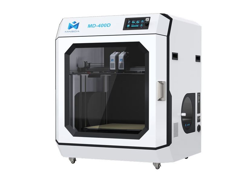


 Manufacturers across aerospace, automotive, machining, plastics, tooling, and medical industries rely on portable 3D scanning arms to improve inspection speed and dimensional accuracy. Among today’s most flexible solutions are Kreon scanning arms, which combine tactile probing and high-speed laser scanning into a single portable metrology platform.


 The Results
 Why This Matters for Marine Manufacturers


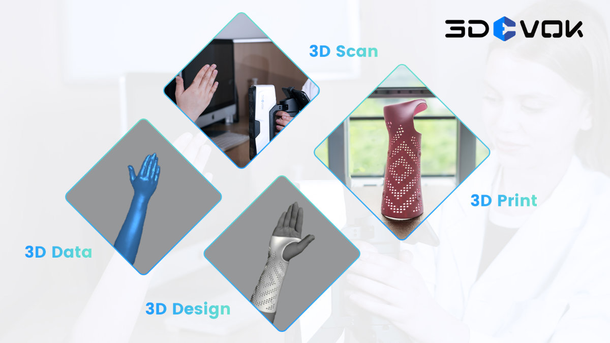
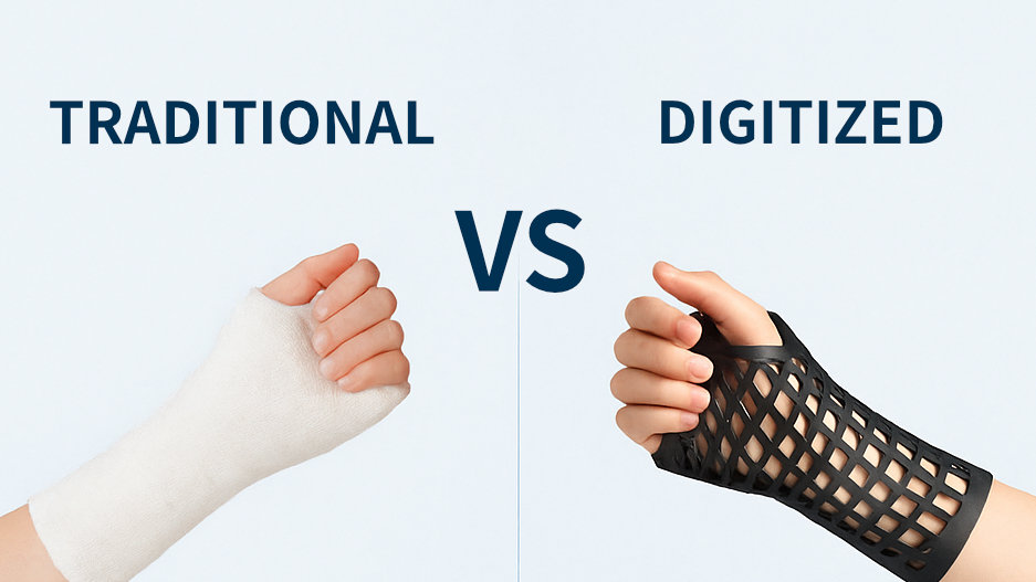 Digital orthotics and prosthetics (O&P) represent a growing frontier in personalized medicine. From injury recovery to post-operative care, the integration of 3D scanning and printing is reducing lead times, improving outcomes, and transforming patient experiences.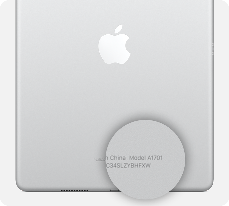


 For a demo of the Artec Leo - Contact info@rapidscan3d.com or (562) 912-3544 Learn more:


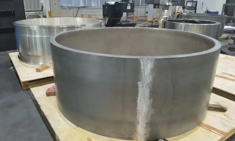

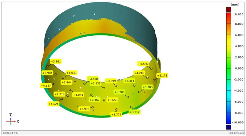

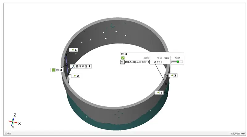
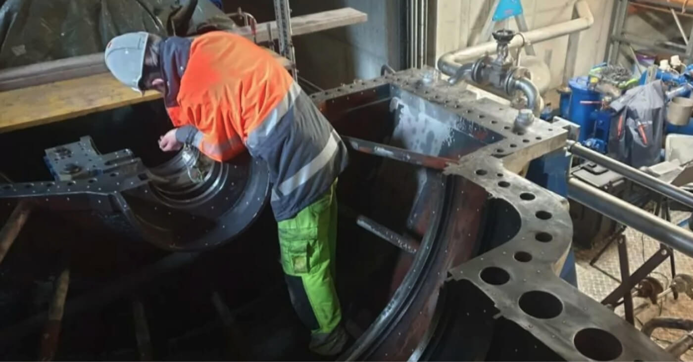
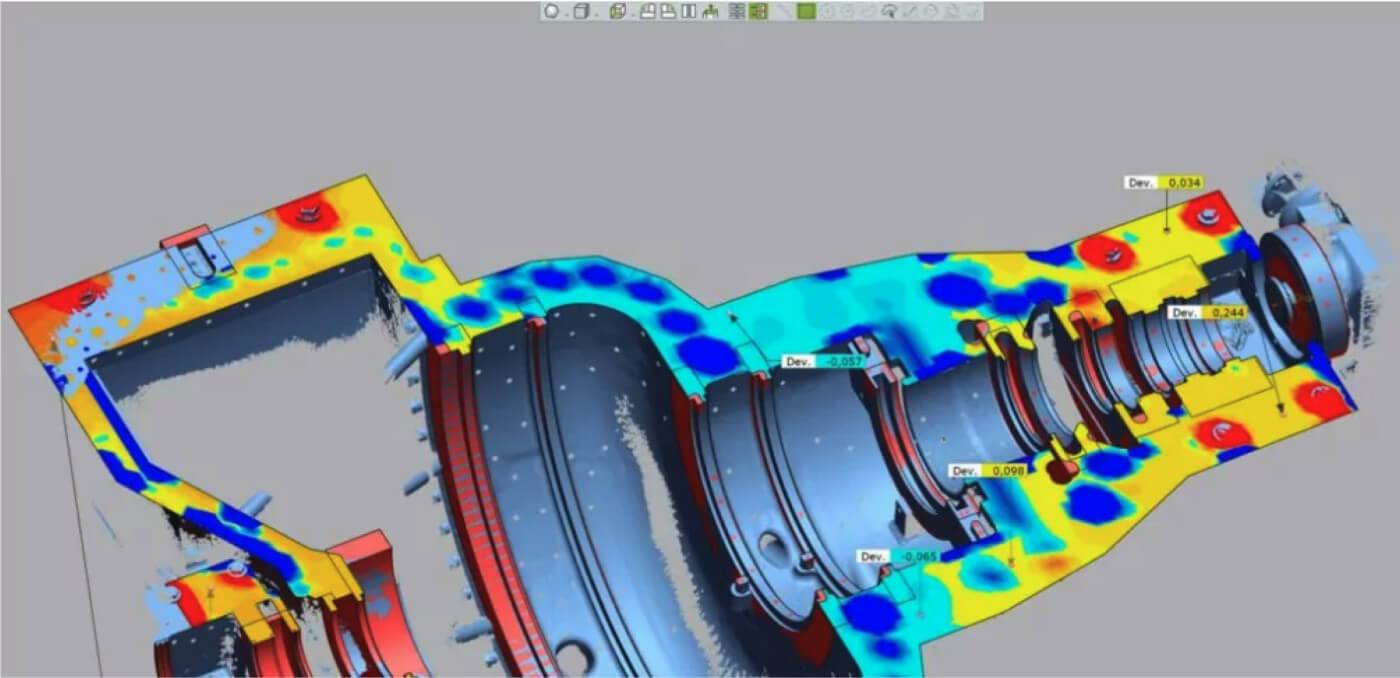
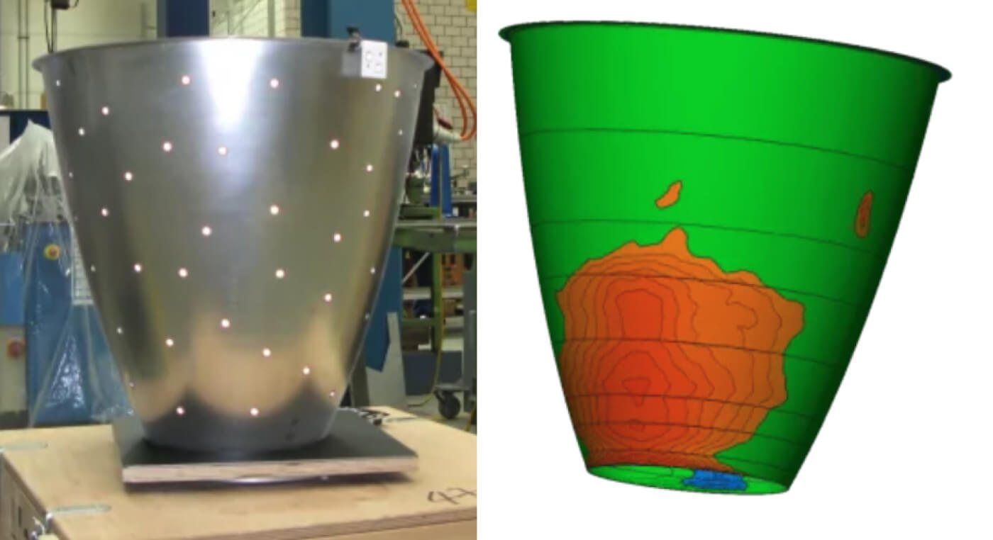
 Facebook
 Twitter
 Linkedin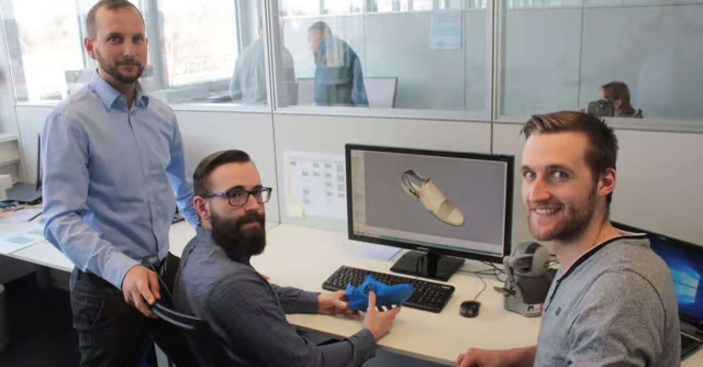
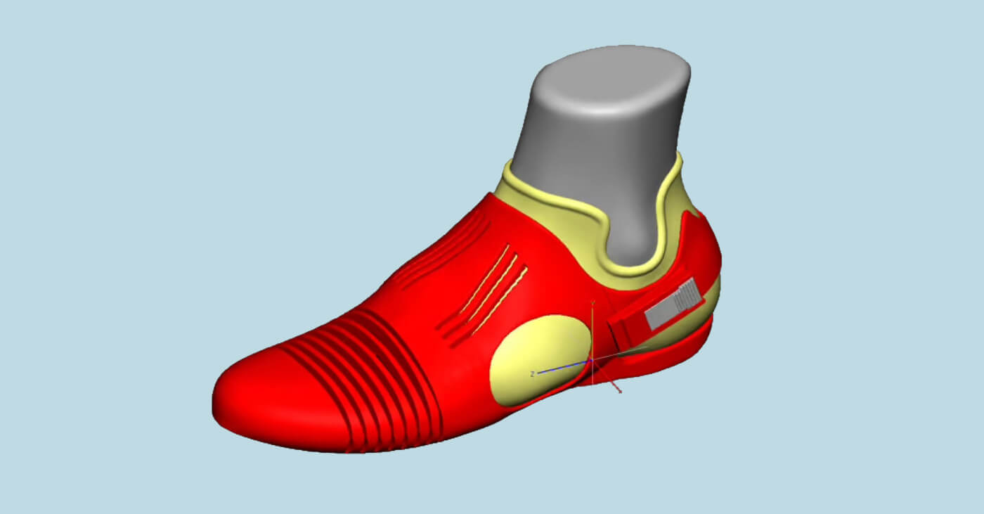


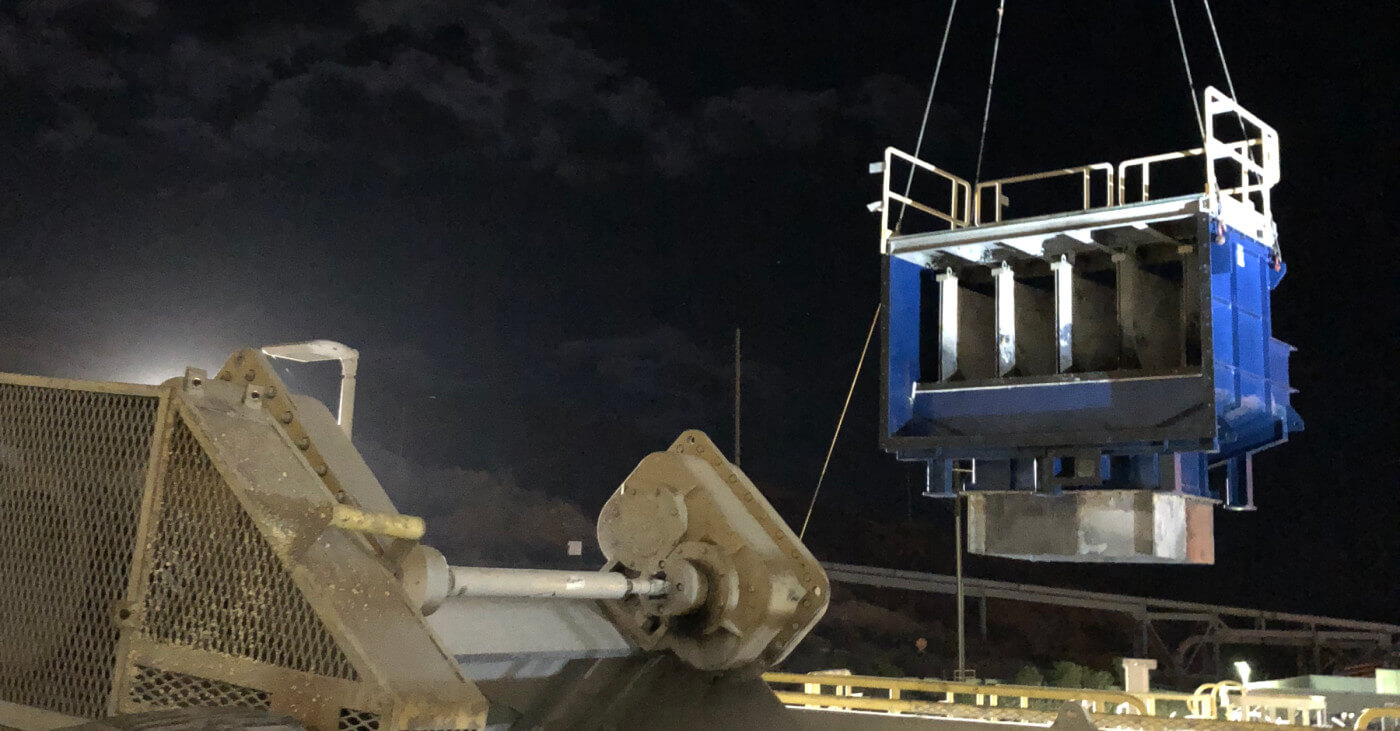
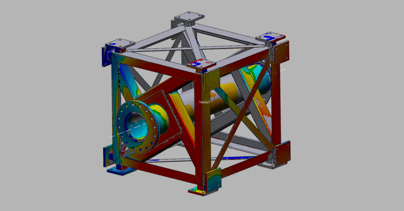 Heat mapping is another advantage that comes with using Design X. “It allows us to set tolerance to plus or minus 1/16 inch and see how far out we are, and if it’s a critical area or non-critical. Heat mapping is a much more efficient way of ensuring that we’re within tolerances than using a tape measure,” Koch explains.
 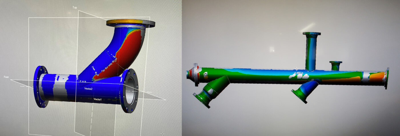 Heat map of existing vs modeled piping system


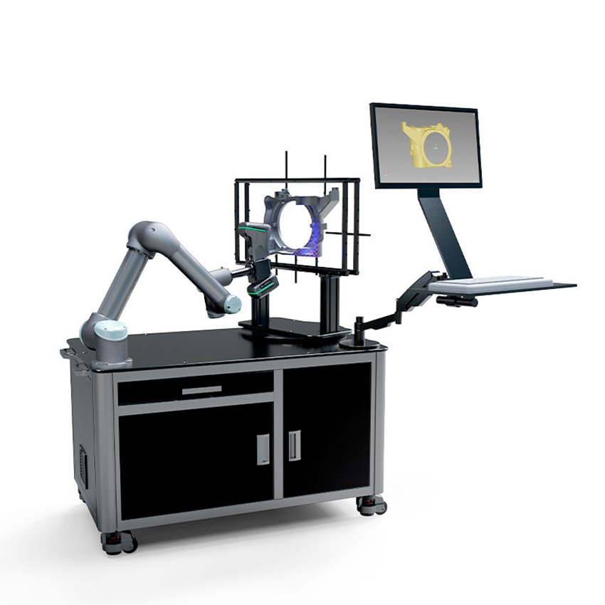
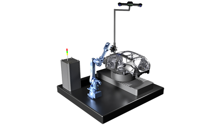

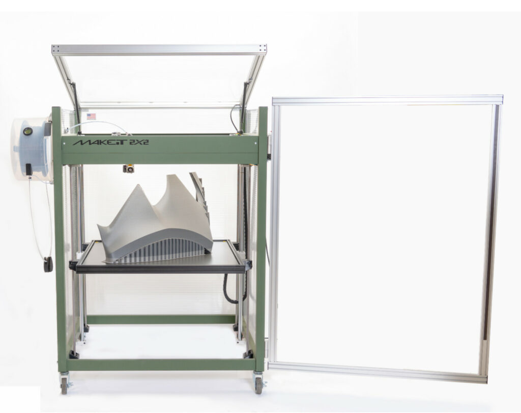


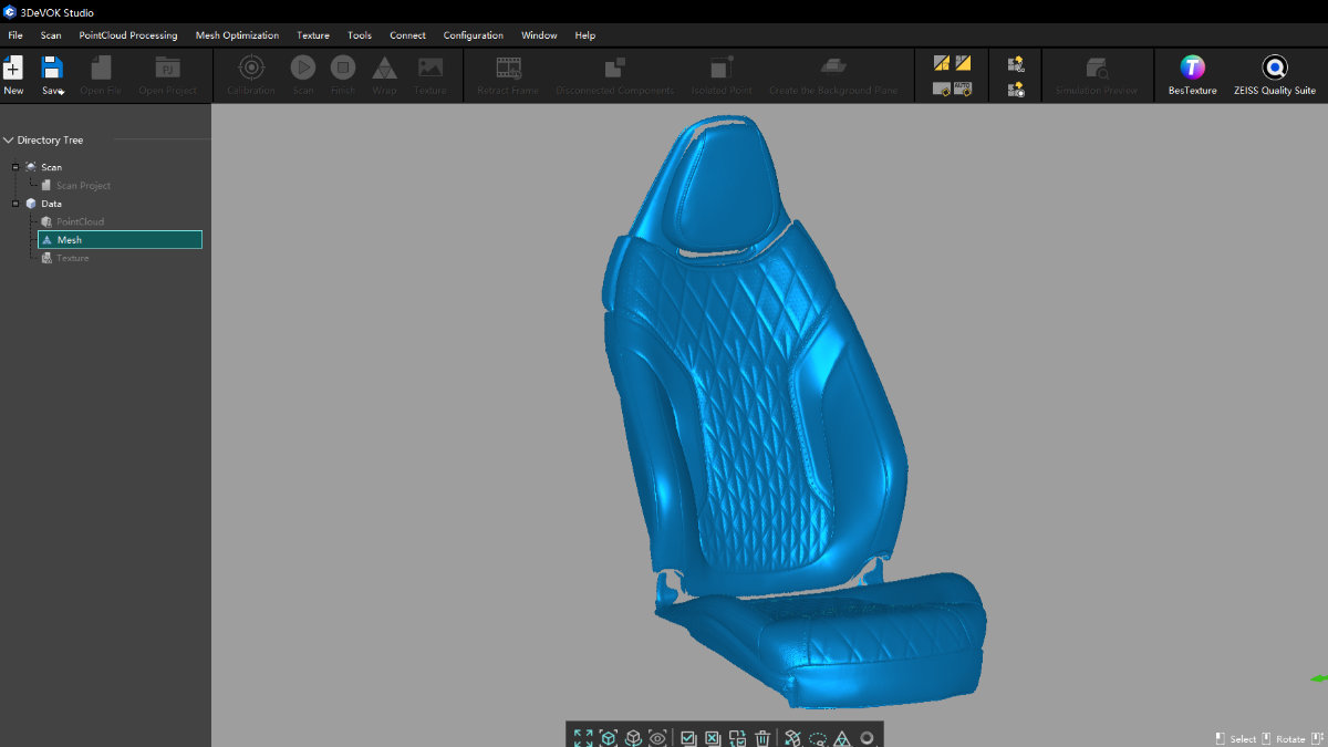


 Revolutionizing Automotive Parts Inspection with Automated 3D Scanning

 Our Turnkey Automated 3D Scanning Solution


 Rapid Scan 3D is an Artec Abassador and Gold Reseller.