



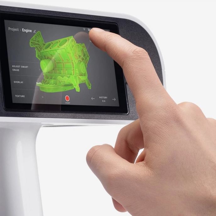
Artec Leo
A wireless handheld structured-light scanner with a built-in display for checking coverage as you scan. It’s useful for mobile work on vehicle panels, equipment housings and other parts with complex surfaces.
Explore Artec Leo

Turn a physical part into CAD you can use. Rapid Scan 3D captures parts, tooling and assemblies, then rebuilds the geometry in Geomagic Design X for replacement parts, design changes and fit-up.
We start by agreeing on what the model needs to capture, which dimensions matter and how you plan to use the files. These examples show common stages of a scan-to-CAD project.
We scan accessible surfaces from multiple angles and check coverage around mating faces, mounting points and other critical features.

We align the scan passes, remove stray data and prepare a polygon mesh. In Geomagic Design X, we orient the mesh to the part’s datums and use it as a reference for modeling.

We use the mesh to fit sketches, solids or freeform surfaces. Then we compare the rebuilt CAD with the scan to review deviations before exporting the agreed deliverables.
We choose the scanner based on the size of the part, surface finish, access and how tightly the critical geometry needs to be measured.
A wireless handheld structured-light scanner with a built-in display for checking coverage as you scan. It’s useful for mobile work on vehicle panels, equipment housings and other parts with complex surfaces.
Explore Artec Leo
These blue-laser systems use optical tracking to capture geometry for parts such as castings, tooling and stamped panels. TrackScan GO also supports larger assemblies. The photo shows NimbleTrack Gen2 in use.
Explore NimbleTrack Gen2 Explore TrackScan GODesign X brings scan cleanup, solid modeling and surfacing into the same workflow. Its feature extraction tools help rebuild geometry such as holes and cylinders. Accuracy Analyzer compares the model with the scan, and LiveTransfer can send feature history to compatible CAD software.
If a part is worn or damaged, tell us which features should match the part as it exists and which need to reflect the intended geometry. An unworn sample, dimensions or a mating part can help us resolve those details.
Send a few photos, approximate dimensions, the features that need to fit and your preferred CAD format. If you already have scan data, tell us what file format you have and what you need modeled. Our team can quote the full scan-to-CAD job or help with modeling only.
Building an in-house workflow? We also supply scanners and software and provide training and support. Talk with our team.